IMMOBILISER SYSTEM, Diagnostic DTC:B2799, B279986
| DTC Code | DTC Name |
|---|---|
| B2799 | Engine Immobiliser System Malfunction |
| B279986 | Engine Immobiliser System Signal (Some Circuit Quantity, Reported via Serial Data) Invalid |
DESCRIPTION
When there is a communication malfunction between the ECM and ID code box (immobiliser code ECU), or when the communication ID codes do not match, the ECM stores this DTC.
| DTC No. | Detection Item | DTC Detection Condition | Trouble Area | Note |
|---|---|---|---|---|
| B2799 | Engine Immobiliser System Malfunction | Either condition is met (1 trip detection logic*1):
|
|
DTC output confirmation operation (Either condition is met):
|
| B279986 | Engine Immobiliser System Signal (Some Circuit Quantity, Reported via Serial Data) Invalid | Either condition is met (1 trip detection logic*1):
|
|
DTC output confirmation operation (Either condition is met):
|
-
*1: Only output while a malfunction is present.
-
*2: w/ Blocking System
| Vehicle Condition when Malfunction Detected | Fail-safe Operation when Malfunction Detected |
|---|---|
| Engine cannot be started | - |
| DTC No. | Data List and Active Test |
|---|---|
|
- |
-
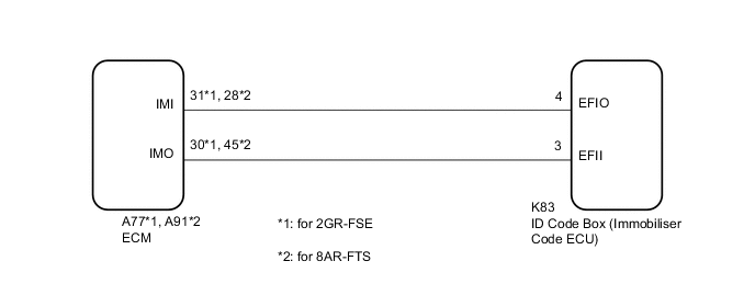
*1: for 2GR-FSE
-
*2: for 8AR-FTS
WIRING DIAGRAM
-
w/o Blocking System
-
w/ Blocking System
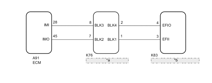
*a Telephone Transceiver Assembly *b ID Code Box (Immobiliser Code ECU)
CAUTION / NOTICE / HINT
Note
-
When using the GTS with the engine switch off, connect the GTS to the DLC3 and turn a courtesy light switch on and off at intervals of 1.5 seconds or less until communication between the GTS and the vehicle begins. Then select Model Code "KEY REGIST" under manual mode and enter the following menus: Body Electrical / Entry&Start(CAN). While using the GTS, periodically turn a courtesy light switch on and off at intervals of 1.5 seconds or less to maintain communication between the GTS and the vehicle.
-
Before replacing the ECM, telephone transceiver assembly* or ID code box (immobiliser code ECU), refer to Service Bulletin.
-
After repair, confirm that no DTCs are output by performing "DTC Output Confirmation Operation."
-
When the telephone transceiver assembly is replaced, it is necessary to set the contract mode.*
-
*: w/ Blocking System
Tech Tips
When DTC B2799*1 or B279986*2 and the certification ECU (smart key ECU assembly) DTC are output simultaneously, first perform troubleshooting for the certification ECU (smart key ECU assembly) DTC.
-
*1: for 2GR-FSE
-
*2: for 8AR-FTS
PROCEDURE
-
SYSTEM CHECK
-
Check the vehicle specification.
Result Result Proceed to w/o Blocking System A w/ Blocking System B
B 
CHECK HARNESS AND CONNECTOR (ECM - TELEPHONE TRANSCEIVER ASSEMBLY) Click here
A 
-
-
REGISTER ECU COMMUNICATION ID
-
Register the ECU communication ID.
Tech Tips
Refer to Service Bulletin.
Result Proceed to NEXT
NEXT
-
-
CLEAR DTC
-
Clear the DTCs.
Powertrain > Engine > Clear DTCsResult Proceed to NEXT
NEXT
-
-
CHECK FOR DTC
-
Perform "DTC Output Confirmation Operation" procedure.
-
Check for DTCs.
Powertrain > Engine > Trouble CodesOK B2799*1 or B279986*2 is not output.
-
*1: for 2GR-FSE
-
*2: for 8AR-FTS
Result Proceed to OK NG -
OK 
END (COMMUNICATION ID REGISTRATION WAS DEFECTIVE)
NG
-
-
CHECK HARNESS AND CONNECTOR (ID CODE BOX (IMMOBILISER CODE ECU) - ECM)
-
Disconnect the K83 ID code box (immobiliser code ECU) connector.
-
Disconnect the A77*1 or A91*2 ECM connector.
-
*1: for 2GR-FSE
-
*2: for 8AR-FTS
-
-
Measure the resistance according to the value(s) in the table below.
Standard Resistance for 2GR-FSE Tester Connection Condition Specified Condition K83-4 (EFIO) - A77-31 (IMI) Always Below 1 Ω K83-3 (EFII) - A77-30 (IMO) Always Below 1 Ω K83-4 (EFIO) or A77-31 (IMI) - Body ground Always 10 kΩ or higher K83-3 (EFII) or A77-30 (IMO) - Body ground Always 10 kΩ or higher for 8AR-FTS Tester Connection Condition Specified Condition K83-4 (EFIO) - A91-31 (IMI) Always Below 1 Ω K83-3 (EFII) - A91-45 (IMO) Always Below 1 Ω K83-4 (EFIO) or A91-31 (IMI) - Body ground Always 10 kΩ or higher K83-3 (EFII) or A91-45 (IMO) - Body ground Always 10 kΩ or higher Result Proceed to OK NG
OK
GO TO STEP 15 Click here
NG
REPAIR OR REPLACE HARNESS OR CONNECTOR
-
-
CHECK HARNESS AND CONNECTOR (ECM - TELEPHONE TRANSCEIVER ASSEMBLY)
-
Disconnect the A91 ECM connector.
-
Disconnect the K76 telephone transceiver assembly connector.
-
Measure the resistance according to the value(s) in the table below.
Standard Resistance Tester Connection Condition Specified Condition A91-45 (IMO) - K76-7 (BLK2) Always Below 1 Ω A91-28 (IMI) - K76-8 (BLK3) Always Below 1 Ω A91-45 (IMO) or K76-7 (BLK2) - Body ground Always 10 kΩ or higher A91-28 (IMI) or K76-8 (BLK3) - Body ground Always 10 kΩ or higher Result Proceed to OK NG
NG
REPAIR OR REPLACE HARNESS OR CONNECTOR
OK
-
-
CHECK HARNESS AND CONNECTOR (ID CODE BOX (IMMOBILISER CODE ECU) - TELEPHONE TRANSCEIVER ASSEMBLY)
-
Disconnect the K83 ID code box (immobiliser code ECU) connector.
-
Disconnect the K76 telephone transceiver assembly connector.
-
Measure the resistance according to the value(s) in the table below.
Standard Resistance Tester Connection Condition Specified Condition K83-3 (EFII) - K76-1 (BLK1) Always Below 1 Ω K83-4 (EFIO) - K76-2 (BLK4) Always Below 1 Ω K83-3 (EFII) or K76-1 (BLK1) - Body ground Always 10 kΩ or higher K83-4 (EFIO) or K76-2 (BLK4) - Body ground Always 10 kΩ or higher Result Proceed to OK NG
NG
REPAIR OR REPLACE HARNESS OR CONNECTOR
OK
-
-
REGISTER ECU COMMUNICATION ID
-
Reregister the ECU communication ID.
Tech Tips
Refer to Service Bulletin.
Result Proceed to NEXT
NEXT
-
-
CLEAR DTC
-
Clear the DTCs.
Powertrain > Engine > Clear DTCsResult Proceed to NEXT
NEXT
-
-
CHECK FOR DTC
-
Check for DTCs.
Powertrain > Engine > Trouble CodesTech Tips
Before checking for DTCs, perform the "DTC Output Confirmation Operation" procedure.
Result Result Proceed to B279986 is not output A B279986 is output B Other DTCs are output C
A
END (COMMUNICATION ID REGISTRATION WAS DEFECTIVE)
C
GO TO DIAGNOSTIC TROUBLE CODE CHART Click here
B
-
-
REPLACE TELEPHONE TRANSCEIVER ASSEMBLY
-
Temporarily replace the telephone transceiver assembly with a new or known good one.
Tech Tips
Refer to Service Bulletin.
Result Proceed to NEXT
NEXT
-
-
REGISTER ECU COMMUNICATION ID
-
Reregister the ECU communication ID.
Tech Tips
Refer to Service Bulletin.
Result Proceed to NEXT
NEXT
-
-
CLEAR DTC
-
Clear the DTCs.
Powertrain > Engine > Clear DTCsResult Proceed to NEXT
NEXT
-
-
CHECK FOR DTC
-
Check for DTCs.
Powertrain > Engine > Trouble CodesTech Tips
Before checking for DTCs, perform the "DTC Output Confirmation Operation" procedure.
OK B279986 is not output. Result Proceed to OK NG
OK
END (TELEPHONE TRANSCEIVER ASSEMBLY WAS DEFECTIVE)
NG
-
-
REPLACE ECM
-
Temporarily replace the ECM with a new one.
for 2GR-FSE: Click here
for 8AR-FTS: Click here
Result Proceed to NEXT
NEXT
-
-
CLEAR DTC
-
Clear the DTCs.
Powertrain > Engine > Clear DTCsResult Proceed to NEXT
NEXT
-
-
CHECK FOR DTC
-
Perform "DTC Output Confirmation Operation" procedure.
-
Check for DTCs.
Powertrain > Engine > Trouble CodesOK B2799 is not output. Result Proceed to OK NG
OK
END (ECM WAS DEFECTIVE)
NG
REPLACE ID CODE BOX (IMMOBILISER CODE ECU)
-