CONDENSER(for 8AR-FTS) INSTALLATION
PROCEDURE
-
INSTALL COOLER CONDENSER ASSEMBLY
-
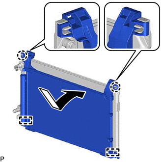
Engage the 2 guides and 2 claws to install the cooler condenser assembly to the intercooler cooling radiator assembly as shown in the illustration.
Note
Do not damage the cooler condenser assembly or intercooler cooling radiator assembly when installing the cooler condenser assembly.
-
-
INSTALL COOLER CONDENSER ASSEMBLY WITH INTERCOOLER COOLING RADIATOR ASSEMBLY
-
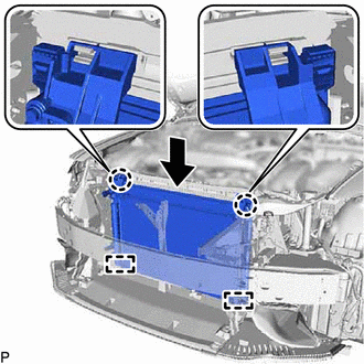
Engage the 2 guides as shown in the illustration.
Note
Do not damage the cooler condenser assembly with intercooler cooling radiator assembly or radiator assembly when installing the cooler condenser assembly with intercooler cooling radiator assembly.
-
Engage the 2 claws to install the cooler condenser assembly with intercooler cooling radiator assembly.
Tech Tips
If a new cooler condenser assembly is installed, add compressor oil to the condenser as follows.
Capacity Add 40 cc (1.35 fl. oz) Refrigerant Compressor Oil HFC-134a (R134a) ND-OIL 8 or equivalent HFO-1234yf (R1234yf) ND-OIL 12 or equivalent
-
-
CONNECT NO. 7 INTERCOOLER COOLING WATER HOSE
-
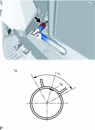
*a View A *b Marking (Orange) *c Clip Installation Angle (90°) Connect the No. 7 intercooler cooling water hose with the marking (orange) facing up and engage the clip within the area shown in the illustration.
Note
Do not apply excessive force to the No. 7 intercooler cooling water hose.
-
-
CONNECT NO. 1 INTERCOOLER COOLING WATER HOSE
-
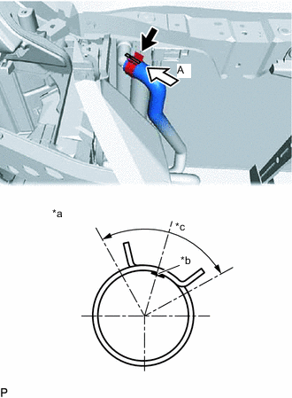
*a View A *b Marking (Orange) *c Clip Installation Angle (90°) Connect the No. 1 intercooler cooling water hose with the marking (orange) facing up and engage the clip within the area shown in the illustration.
Note
Do not apply excessive force to the No. 1 intercooler cooling water hose.
-
-
CONNECT NO. 1 COOLER REFRIGERANT DISCHARGE HOSE
-
Remove the vinyl tape from the No. 1 cooler refrigerant discharge hose and the connecting part of the cooler condenser assembly.
-
Sufficiently apply compressor oil to a new O-ring and the fitting surface of the hose joint.
Refrigerant Compressor Oil HFC-134a (R134a) ND-OIL 8 or equivalent HFO-1234yf (R1234yf) ND-OIL 12 or equivalent -
Install the O-ring to the No. 1 cooler refrigerant discharge hose.
-
Connect the No. 1 cooler refrigerant discharge hose to the cooler condenser assembly with the bolt.
- Torque:
- 5.4 N*m { 55 kgf*cm, 48 in.*lbf }
-
-
CONNECT LIQUID TUBE SUB-ASSEMBLY A
-
Remove the vinyl tape from the liquid tube sub-assembly A and the connecting part of the cooler condenser assembly.
-
Sufficiently apply compressor oil to a new O-ring and the fitting surface of the tube joint.
Refrigerant Compressor Oil HFC-134a (R134a) ND-OIL 8 or equivalent HFO-1234yf (R1234yf) ND-OIL 12 or equivalent -
Install the O-ring to the liquid tube sub-assembly A.
-
Connect the liquid tube sub-assembly A to the cooler condenser assembly with the 2 bolts.
- Torque:
- 5.4 N*m { 55 kgf*cm, 48 in.*lbf }
-
Engage the claw to close the service hole cover.
-
-
INSTALL UPPER RADIATOR SUPPORT SUB-ASSEMBLY
-
CONNECT ENGINE ROOM MAIN WIRE
-
INSTALL HOOD LOCK ASSEMBLY
-
CONNECT HOOD LOCK CONTROL CABLE ASSEMBLY
-
INSTALL HOOD LOCK RELEASE LEVER PROTECTOR
-
INSTALL INLET NO. 1 AIR CLEANER
-
INSTALL FRONT BUMPER ASSEMBLY
for Standard:
for Sport Package:
-
ADD COOLANT (for Intercooler)
-
INSPECT FOR COOLANT LEAK (for Intercooler)
-
CHARGE AIR CONDITIONING SYSTEM WITH REFRIGERANT (for HFC-134a(R134a))
-
CHARGE AIR CONDITIONING SYSTEM WITH REFRIGERANT (for HFO-1234yf(R1234yf))
-
WARM UP ENGINE (for HFC-134a(R134a))
-
WARM UP ENGINE (for HFO-1234yf(R1234yf))
-
INSPECT FOR REFRIGERANT LEAK (for HFC-134a(R134a))
-
INSPECT FOR REFRIGERANT LEAK (for HFO-1234yf(R1234yf))
-
ADJUST HOOD SUB-ASSEMBLY