ENGINE UNIT REMOVAL

CAUTION / NOTICE / HINT
CAUTION:
-
The exhaust valve is filled with sodium. Sodium is a strong alkali which can produce a dangerous chemical reaction. Be very careful when handling and disposing of it.
-
Do not intentionally expose the sodium in exhaust valve. If sodium enters your eyes, vision loss may occur. If sodium contacts your skin, burns may occur. If a fire occurs due to a chemical reaction with sodium, burns may occur.
-
If the sodium in the exhaust valve is exposed, perform all necessary preparations to safely remove and dispose of the sodium.
-
When removing a damaged exhaust valve, always wear rubber gloves and safety glasses.
-
Do not intentionality cut or break open the exhaust valve to remove the sodium.
Tech Tips
-
The sodium inside the exhaust valve is safe as long as it remains sealed inside the exhaust valve.
-
Exhaust valves filled with sodium can be identified by their "NA" identification mark.
-
Removal of the exhaust valve:
-
Disposal of the exhaust valve:
PROCEDURE
-
REMOVE GENERATOR ASSEMBLY
-
REMOVE COMPRESSOR AND MAGNETIC CLUTCH
-
REMOVE NO. 1 COMPRESSOR MOUNTING BRACKET
-
REMOVE NO. 2 WATER BY-PASS PIPE
-
REMOVE WATER BY-PASS PIPE ASSEMBLY
-
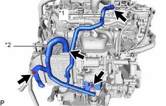
*1 No. 2 Turbo Water Hose *2 No. 9 Water By-pass Hose Slide the clip and disconnect the No. 2 turbo water hose from the No. 1 turbo water pipe sub-assembly.
-
Slide the clip and disconnect the No. 9 water by-pass hose from the intercooler assembly.
-
Remove the 2 bolts and water by-pass pipe assembly from the intercooler assembly and No. 2 air tube.
-
-
REMOVE PURGE VALVE (PURGE VSV)
-
w/ Canister Pump Module:
-
w/o Canister Pump Module:
-
-
DISCONNECT NO. 2 VACUUM TRANSMITTING HOSE ASSEMBLY
-
DISCONNECT VACUUM TRANSMITTING HOSE ASSEMBLY
-
REMOVE NO. 2 VENTILATION HOSE
-
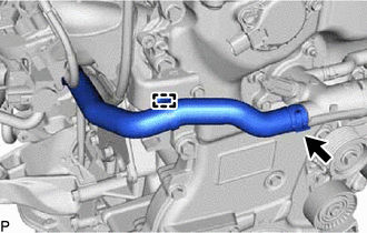
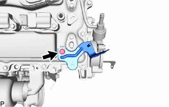
DISCONNECT NO. 3 WATER BY-PASS HOSE
-
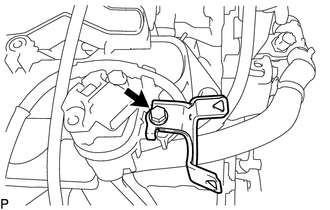
Disengage the clamp from the engine oil level dipstick guide.
-
Slide the clip and disconnect the No. 3 water by-pass hose from the water outlet sub-assembly.
-
-
REMOVE INTAKE MANIFOLD WITH INTERCOOLER ASSEMBLY AND THROTTLE WITH MOTOR BODY ASSEMBLY
-
Remove the bolt and wire harness clamp bracket from the intake manifold with intercooler assembly and throttle with motor body assembly.
-
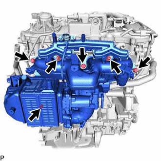
Remove the 4 bolts, 2 nuts and intake manifold with intercooler assembly and throttle with motor body assembly.
-
Remove the 2 No. 1 intake manifold to head gaskets from the intake manifold with intercooler assembly and throttle with motor body assembly.
-
-
REMOVE FRONT ENGINE MOUNTING HEAT INSULATOR LH (w/ Front Engine Mounting Heat Insulator LH)
-
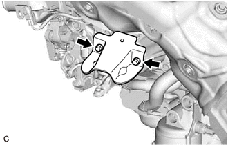
Remove the 2 bolts and front engine mounting heat insulator LH from the front No. 1 engine mounting bracket LH.
-
-
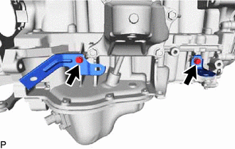
REMOVE FRONT NO. 1 ENGINE MOUNTING BRACKET LH
-
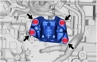
Remove the 4 bolts and front No. 1 engine mounting bracket LH from the cylinder block sub-assembly.
-
-
REMOVE FRONT NO. 1 ENGINE MOUNTING BRACKET RH
-
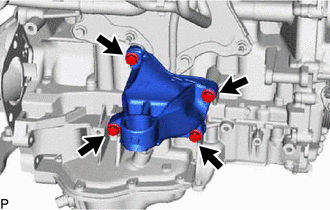
Remove the 4 bolts and front No. 1 engine mounting bracket RH from the cylinder block sub-assembly.
-
-
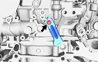
REMOVE ENGINE OIL LEVEL DIPSTICK GUIDE
-
Remove the engine oil level dipstick.
-
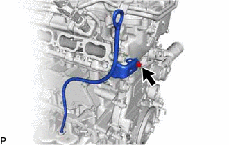
Remove the bolt and engine oil level dipstick guide.
-
Remove the O-ring from the engine oil level dipstick guide.
-
-
REMOVE IGNITION COIL ASSEMBLY
-
REMOVE VENTILATION HOSE
-
REMOVE NO. 4 VENTILATION HOSE
-
REMOVE NO. 5 EXHAUST MANIFOLD HEAT INSULATOR
-
REMOVE OUTLET COMPRESSOR ELBOW
-
Remove the 2 nuts and outlet compressor elbow from the turbocharger sub-assembly.
-
Remove the gasket from the turbocharger sub-assembly.
-
-
REMOVE NO. 1 HEAT INSULATOR BRACKET
-
REMOVE NO. 2 HEAT INSULATOR BRACKET
-
DISCONNECT INLET TURBO OIL PIPE SUB-ASSEMBLY
-
REMOVE TURBOCHARGER SUB-ASSEMBLY
-
REMOVE NO. 3 EXHAUST MANIFOLD HEAT INSULATOR
-
REMOVE SENSOR WIRE
-
Disconnect the fuel pressure sensor connector.
-
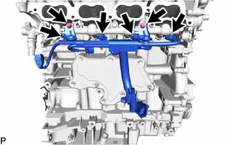
Remove the 2 bolts and disconnect the sensor wire from the fuel delivery pipe sub-assembly.
-
Disconnect the 4 direct fuel injector assembly connectors and remove the sensor wire.
-
-
REMOVE WIRE HARNESS CLAMP BRACKET
-
for Engine Front Side:
-
Disconnect the oil pressure sender gauge assembly connector.
-
Remove the bolt and wire harness clamp bracket from the timing chain cover assembly.
-
-
for Engine Upper Side:
-
Remove the bolt and wire harness clamp bracket from the cylinder head cover sub-assembly.
-
-
for Engine RH Side:
-
Remove the 2 bolts and 2 wire harness clamp brackets from the stiffening crankcase assembly.
-
-
for Engine Rear Side:
-
Remove the bolt and wire harness clamp bracket from the cylinder head sub-assembly.
-
-
-
REMOVE OIL FILLER CAP SUB-ASSEMBLY
-
Remove the oil filler cap sub-assembly from the cylinder head cover sub-assembly.
-
-
REMOVE OIL FILLER CAP GASKET
-
Remove the oil filler cap gasket from the oil filler cap sub-assembly.
-
-
REMOVE IDLER PULLEY SUB-ASSEMBLY
-
REMOVE V-RIBBED BELT TENSIONER ASSEMBLY
-
REMOVE NO. 1 TURBO WATER PIPE SUB-ASSEMBLY
-
REMOVE AIR CLEANER BRACKET
-
REMOVE NO. 1 FUEL PIPE SUB-ASSEMBLY (for High Pressure)
-
REMOVE FUEL DELIVERY PIPE (for Port Injection)
-
REMOVE PORT FUEL INJECTOR ASSEMBLY
-
REMOVE FUEL DELIVERY PIPE SUB-ASSEMBLY (for Direct Injection)
-
REMOVE DIRECT FUEL INJECTOR ASSEMBLY
-
REMOVE FUEL INJECTOR SEAL (for Direct Injection)
-
REMOVE FUEL PUMP ASSEMBLY (for High Pressure)
-
REMOVE VACUUM PUMP ASSEMBLY
-
REMOVE NO. 9 ENGINE WIRE
-
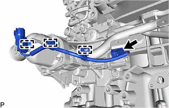
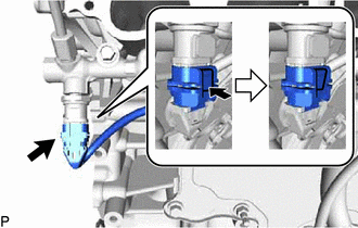
Disconnect the oil pressure switching valve assembly connector.
-
Remove the 3 clamps and No. 9 engine wire from the No. 1 water by-pass pipe and water inlet housing.
-
-
REMOVE NO. 1 WATER BY-PASS PIPE
-
REMOVE NO. 4 WATER BY-PASS PIPE
-
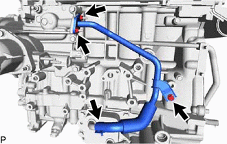
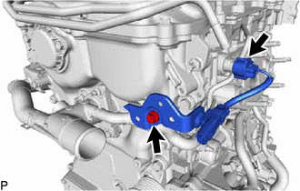
Slide the clip and disconnect the No. 4 water by-pass pipe from the oil cooler assembly.
-
Remove the 2 nuts, bolt and No. 4 water by-pass pipe from the cylinder block sub-assembly and water inlet housing.
-
Remove the gasket from the water inlet housing.
-
-
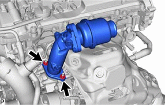
REMOVE OIL PRESSURE SWITCHING VALVE ASSEMBLY
-
REMOVE WATER INLET HOUSING SUB-ASSEMBLY
-
REMOVE THERMOSTAT (for Cylinder Block)