PROCEDURE
- Click here
INSTALL ENGINE WATER PUMP ASSEMBLY
-
Remove the adhesive from the threads of the bolt and the bolt hole of the timing chain cover sub-assembly.
-
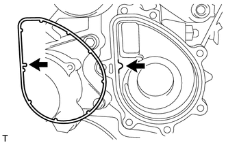
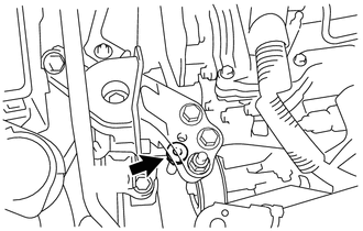
Install a new gasket to the timing chain cover sub-assembly so that the protrusions indicated by the arrows in the illustration are aligned.
-
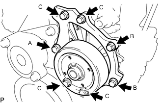
Apply adhesive to 2 or 3 threads of the bolt labeled A.
Adhesive Toyota Genuine Adhesive 1324, Three Bond 1324 or equivalent Standard Bolt Length Item Specified Condition Bolt A and C 45 mm (1.77 in.) Bolt B 30 mm (1.18 in.) -
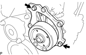
Install the engine water pump assembly with the 2 bolts indicated by the arrows in the illustration.
23 N*m 229 kgf*cm 17 ft.*lbf -
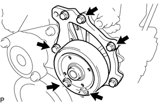
Install the 5 bolts.
23 N*m 229 kgf*cm 17 ft.*lbf
-
- Click here
INSTALL NO. 2 IDLER PULLEY SUB-ASSEMBLY
-
Install the No. 2 idler pulley sub-assembly and No. 2 idler pulley cover plate with the bolt.
40 N*m 408 kgf*cm 30 ft.*lbf
-
- Click here
INSTALL NO. 1 IDLER PULLEY SUB-ASSEMBLY
- Click here
INSTALL IDLER PULLEY COVER PLATE
- Click here
INSTALL ENGINE MOUNTING SPACER
-
Install the engine mounting spacer with the 2 bolts.
95 N*m 969 kgf*cm 70 ft.*lbf
-
- Click here
INSTALL ENGINE MOUNTING INSULATOR SUB-ASSEMBLY RH
-
Install the engine mounting insulator sub-assembly RH with the 5 bolts and nut.
Bolt and Nut 95 N*m 969 kgf*cm 70 ft.*lbf -
Remove the jack.
-
Tighten the 4 bolts and 2 nuts to the front engine mounting insulator and rear engine mounting insulator.
95 N*m 969 kgf*cm 70 ft.*lbf -
Install the nut.
52 N*m 530 kgf*cm 38 ft.*lbf
-
- Click here
INSTALL OIL PAN INSULATOR
- Click here
INSTALL FAN AND GENERATOR V BELT
- Click here
INSTALL FRONT SUSPENSION MEMBER REINFORCEMENT RH
- Click here
INSTALL RADIATOR RESERVOIR ASSEMBLY
- Click here
ADD ENGINE COOLANT
- Click here
INSPECT FOR COOLANT LEAK
- Click here
INSTALL NO. 1 ENGINE COVER
- Click here
INSTALL REAR ENGINE UNDER COVER RH
- Click here
INSTALL NO. 1 ENGINE UNDER COVER