СИСТЕМА ECD, Diagnostic DTC:P245A
| DTC Code | DTC Name |
|---|---|
| P245A | Exhaust Gas Recirculation Cooler Bypass Control Circuit / Open Bank 1 |
DESCRIPTION
In order to lower the temperature of the recirculated exhaust gas and thus further reduce nitrogen oxide emissions, the exhaust gas is recirculated through the EGR cooler assembly. With this flap, the exhaust gas is guided at low temperatures past the cooling fins into a bypass channel and thus not cooled. Only at higher engine temperatures does the ECM open the bypass flap and the exhaust gas is cooled again.
This function reduces the HC emissions in cold operating conditions. The EGR cooler bypass switching valve assembly is opened during EGR operation if the coolant temperature is lower than 50°C (122°F).
| DTC No. | Detection Item | DTC Detection Condition | Trouble Area | MIL | Memory |
|---|---|---|---|---|---|
| P245A | Exhaust Gas Recirculation Cooler Bypass Control Circuit / Open Bank 1 | Open detected in EGR cooler bypass switching valve assembly circuit for 0.22 seconds. (3 trip detection logic) |
|
Does not come on | DTC stored |
| DTC No. | Data List |
|---|---|
| P245A | EGR Cooler Bypass Valve |
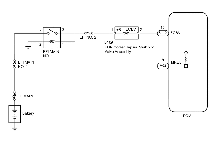
WIRING DIAGRAM
CAUTION / NOTICE / HINT
Tech Tips
-
When the ECM must be replaced, before replacing the ECM, perform the "Learning Values Save" function using the GTS. Then after installing the new ECM, perform all of the initialization/registrations for the "Learning Values Write" function by following the instructions shown on the GTS display.
-
Read freeze frame data using the GTS. Freeze frame data records the engine condition when malfunctions are detected. When troubleshooting, freeze frame data can help determine if the vehicle was moving or stationary, if the engine was warmed up or not, and other data from the time the malfunction occurred.
PROCEDURE
-
INSPECT EGR COOLER BYPASS SWITCHING VALVE ASSEMBLY
-
Inspect the EGR cooler bypass switching valve assembly.
Result Proceed to OK NG
NG 
REPLACE EGR COOLER BYPASS SWITCHING VALVE ASSEMBLY Click here
OK 
-
-
CHECK HARNESS AND CONNECTOR (EGR COOLER BYPASS SWITCHING VALVE ASSEMBLY - ECM)
-
Disconnect the EGR cooler bypass switching valve assembly connector.
-
Disconnect the ECM connector.
-
Measure the resistance according to the value(s) in the table below.
Standard Resistance Tester Connection Condition Specified Condition B109-2 (ECBV) - B112-16 (ECBV) Always Below 1 Ω B109-2 (ECBV) or B112-16 (ECBV) - Body ground Always 10 kΩ or higher Result Proceed to OK NG
NG
REPAIR OR REPLACE HARNESS OR CONNECTOR Click here
OK
-
-
CHECK HARNESS AND CONNECTOR (POWER SOURCE)
-
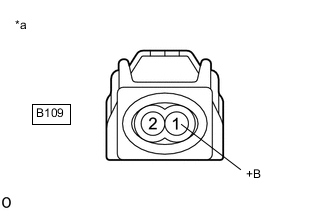
*a Front view of wire harness connector
(to EGR Cooler Bypass Switching Valve Assembly)
Disconnect the EGR cooler bypass switching valve assembly connector.
-
Measure the voltage according to the value(s) in the table below.
Standard Voltage Tester Connection Switch Condition Specified Condition B109-1 (+B) - Body ground Ignition switch ON 11 to 14 V Result Proceed to OK NG
NG
CHECK HARNESS AND CONNECTOR (EGR COOLER BYPASS SWITCHING VALVE ASSEMBLY - EFI MAIN NO. 1 RELAY) Click here
OK
-
-
REPLACE EGR COOLER BYPASS SWITCHING VALVE ASSEMBLY
-
Replace the EGR cooler bypass switching valve assembly.
Result Proceed to NEXT
NEXT
-
-
CHECK WHETHER DTC OUTPUT RECURS (DTC P245A)
-
Connect the GTS to the DLC3.
-
Turn the ignition switch to ON and turn the GTS on.
-
Clear the DTCs.
Powertrain > Engine and ECT > Clear DTCs -
Turn the ignition switch off and wait for 60 seconds or more [A].
-
Perform road test [B].
-
Repeat [A] and [B] for the number of trips detected.
-
Enter the following menus: Powertrain / Engine and ECT / Trouble Codes.
Powertrain > Engine and ECT > Trouble Codes -
Read the DTCs.
Result Result Proceed to No DTC output A DTC P245A B
A 
END
B
-
-
REPLACE ECM
-
Replace the ECM.
Result Proceed to NEXT
NEXT
GO TO STEP 11 Click here
-
-
CHECK HARNESS AND CONNECTOR (EGR COOLER BYPASS SWITCHING VALVE ASSEMBLY - EFI MAIN NO. 1 RELAY)
-
Disconnect the EGR cooler bypass switching valve assembly connector.
-
Remove the EFI MAIN NO. 1 relay from the engine room relay block and junction block.
-
Measure the resistance according to the value(s) in the table below.
Standard Resistance Tester Connection Condition Specified Condition B109-1 (+B) - 3 (EFI MAIN NO. 1 relay holder) Always Below 1 Ω B109-1 (+B) or 3 (EFI MAIN NO. 1 relay holder) - Body ground Always 10 kΩ or higher Result Proceed to OK NG
NG
GO TO STEP 9 Click here
OK
-
-
CHECK ECM POWER SOURCE CIRCUIT
-
Check the ECM power source circuit.
Result Proceed to NEXT
NEXT
GO TO STEP 11 Click here
-
-
REPAIR OR REPLACE HARNESS OR CONNECTOR
-
Repair or replace the harness or connector.
Result Proceed to NEXT
NEXT
GO TO STEP 11 Click here
-
-
REPLACE EGR COOLER BYPASS SWITCHING VALVE ASSEMBLY
-
Replace the EGR cooler bypass switching valve assembly.
Result Proceed to NEXT
NEXT
-
-
CONFIRM WHETHER MALFUNCTION HAS BEEN SUCCESSFULLY REPAIRED
-
Connect the GTS to the DLC3.
-
Turn the ignition switch to ON and turn the GTS on.
-
Clear the DTCs.
Powertrain > Engine and ECT > Clear DTCs -
Turn the ignition switch off and wait for 60 seconds or more [A].
-
Perform road test [B].
-
Repeat [A] and [B] for the number of trips detected.
-
Enter the following menus: Powertrain / Engine and ECT / Trouble Codes.
Powertrain > Engine and ECT > Trouble Codes -
Confirm that the DTC is not output again.
Result Proceed to NEXT
NEXT
END
-