LIGHTING SYSTEM Hazard Warning Switch Circuit
DESCRIPTION
The combination meter receives hazard warning signal switch information signals and illuminates the hazard warning light(s).
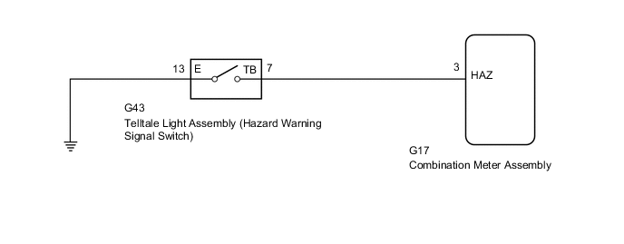
WIRING DIAGRAM
PROCEDURE
-
READ VALUE USING GTS (HAZARD WARNING SIGNAL SWITCH)
-
Using the GTS, read the Data List.
Body Electrical > Combination Meter > Data ListTester Display Measurement Item Range Normal Condition Diagnostic Note Hazard Flasher Switch Hazard warning signal switch signal ON or OFF ON: Hazard warning signal switch on
OFF: Hazard warning signal switch off
-
Body Electrical > Combination Meter > Data ListTester Display Hazard Flasher Switch OK The display is as specified in the normal condition column. Result Proceed to OK NG
OK 
PROCEED TO NEXT SUSPECTED AREA SHOWN IN PROBLEM SYMPTOMS TABLE Click here
NG 
-
-
INSPECT TELLTALE LIGHT ASSEMBLY (HAZARD WARNING SIGNAL SWITCH)
-
Remove the telltale light assembly (hazard warning signal switch).
-
Inspect the telltale light assembly (hazard warning signal switch).
Result Proceed to OK NG
NG
REPLACE TELLTALE LIGHT ASSEMBLY (HAZARD WARNING SIGNAL SWITCH) Click here
OK
-
-
CHECK HARNESS AND CONNECTOR (TELLTALE LIGHT ASSEMBLY [HAZARD WARNING SIGNAL SWITCH] - COMBINATION METER ASSEMBLY AND BODY GROUND)
-
Disconnect the G43 telltale light assembly (hazard warning signal switch) connector.
-
Disconnect the G17 combination meter assembly connector.
-
Measure the resistance according to the value(s) in the table below.
Standard Resistance Tester Connection Condition Specified Condition G17-3 (HAZ) - G43-7 (TB) Always Below 1 Ω G43-13 (E) - Body ground Always Below 1 Ω G17-3 (HAZ) - Body ground Always 10 kΩ or higher Result Proceed to OK NG
OK
REPLACE COMBINATION METER ASSEMBLY Click here
NG
REPAIR OR REPLACE HARNESS OR CONNECTOR
-