IMMOBILISER SYSTEM(w/o Entry and Start System), Diagnostic DTC:B2799
| DTC Code | DTC Name |
|---|---|
| B2799 | Engine Immobiliser System Malfunction |
DESCRIPTION
The ECM stores this DTC when the communication line between the ECM and transponder key ECU assembly is malfunctioning or the communication ID of the ECM and transponder key ECU assembly do not match.
| DTC No. | Detection Item | DTC Detection Condition | Trouble Area | Note |
|---|---|---|---|---|
| B2799 | Engine Immobiliser System Malfunction | One of the following conditions is met:
|
|
DTC Output Confirmation Operation: |
-
*3: w/ Blocking System
| Vehicle Condition when Malfunction Detected | Fail-safe Operation when Malfunction Detected |
|---|---|
| Engine cannot be started | - |
| DTC No. | Data List and Active Test |
|---|---|
| B2799 | - |
WIRING DIAGRAM
-
1. w/o Blocking System
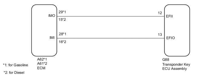
-
2. w/ Blocking System
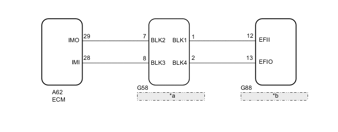
*a Telephone Transceiver Assembly *b Transponder Key ECU Assembly
CAUTION / NOTICE / HINT
Note
-
If the transponder key ECU assembly or ECM is replaced, refer to the Service Bulletin.
-
After repair, confirm that no DTCs are output by performing "DTC Output Confirmation Operation".
-
When using the GTS with the vehicle ignition switch off, connect the GTS to the vehicle and turn a courtesy light switch on and off at intervals of 1.5 seconds or less until communication between the GTS and the vehicle begins. Then select the Model Code "KEY REGIST" under manual mode and enter the following menus: Body Electrical / Immobiliser. While using the GTS, periodically turn a courtesy light switch on and off at intervals of 1.5 seconds or less to maintain communication between the GTS and the vehicle.
Tech Tips
If transponder key ECU assembly DTCs are output simultaneously, troubleshoot the transponder key ECU assembly DTCs first.
PROCEDURE
-
CLEAR DTC
-
Clear the DTCs.
Powertrain > Engine and ECT > Clear DTCs
Powertrain > Engine > Clear DTCsResult Proceed to NEXT
NEXT 
-
-
CHECK FOR DTC
-
Start the engine.
-
Check for DTCs.
Powertrain > Engine and ECT > Trouble Codes
Powertrain > Engine > Trouble CodesTech Tips
Before checking for DTCs, perform the "DTC Output Confirmation Operation" procedure.
OK B2799 is not output. Result Proceed to OK NG (DTC B2799 is output) NG (Other DTCs are output)
OK 
USE SIMULATION METHOD TO CHECK Click here
NG (Other DTCs are output)
GO TO DIAGNOSTIC TROUBLE CODE CHART Click here
NG (DTC B2799 is output)
-
-
REGISTER ECU COMMUNICATION ID
-
Reregister the ECU communication ID.
Tech Tips
Refer to the Service Bulletin.
Result Proceed to NEXT
NEXT
-
-
CHECK WHETHER ENGINE STARTS
-
Using a registered key, turn the ignition switch to ON.
-
Check that the engine starts 5 seconds after the ignition switch was turned to ON.
OK Engine starts normally. Result Proceed to OK NG
OK
END (COMMUNICATION ID REGISTRATION WAS DEFECTIVE)
NG
-
-
INSPECT ECM (IMO TERMINAL VOLTAGE)
-
Disconnect the A62*1 or A61*2 ECM connector.
-
*1: for Gasoline
-
*2: for Diesel
-
-
Turn the ignition switch to ON.
-
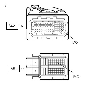
*A for Gasoline *B for Diesel *a Front view of wire harness connector
(to ECM)
Measure the voltage according to the value(s) in the table below.
Standard Voltage Tester Connection Condition Result A62-29 (IMO) - Body ground*1
A61-15 (IMO) - Body ground*2
Ignition switch turned to ON using registered key Terminal IMO stuck low (2.4 V or less) Terminal IMO stuck high (12 V) or abnormal waveform
-
*1: for Gasoline
-
*2: for Diesel
Result Result Proceed to Terminal IMO stuck low (2.4 V or less) (w/ Blocking System) A Terminal IMO stuck low (2.4 V or less) (w/o Blocking System) B Terminal IMO stuck high (12 V) or abnormal waveform (w/o Blocking System) C Terminal IMO stuck high (12 V) or abnormal waveform (w/ Blocking System) D -
B 
CHECK HARNESS AND CONNECTOR (TRANSPONDER KEY ECU - ECM) Click here
C
REPLACE ECM Click here
D
REPLACE ECM Click here
A
-
-
CHECK HARNESS AND CONNECTOR (TELEPHONE TRANSCEIVER ASSEMBLY - TRANSPONDER KEY ECU AND ECM)
-
Disconnect the G58 telephone transceiver assembly connector.
-
Disconnect the G58 transponder key ECU assembly connector.
-
Disconnect the A62 ECM connector.
-
Measure the resistance according to the value(s) in the table below.
Standard Resistance Tester Connection Condition Specified Condition G58-1 (BLK1) - G88-12 (EFII) Always Below 1 Ω G58-7 (BLK2) - A62-29 (IMO) Always Below 1 Ω G58-8 (BLK3) - A62-28 (IMI) Always Below 1 Ω G58-2 (BLK4) - G88-13 (EFIO) Always Below 1 Ω G58-1 (BLK1) - Body ground Always 10 kΩ or higher G58-7 (BLK2) - Body ground Always 10 kΩ or higher G58-8 (BLK3) - Body ground Always 10 kΩ or higher G58-2 (BLK4) - Body ground Always 10 kΩ or higher G88-12 (EFII) - Body ground Always 10 kΩ or higher G88-13 (EFIO) - Body ground Always 10 kΩ or higher A62-28 (IMI) - Body ground Always 10 kΩ or higher A62-29 (IMO) - Body ground Always 10 kΩ or higher Result Proceed to OK NG
NG
REPAIR OR REPLACE HARNESS OR CONNECTOR
OK
-
-
REPLACE TRANSPONDER KEY ECU ASSEMBLY
-
Replace the transponder key ECU assembly with a new one.
Tech Tips
Refer to the Service Bulletin.
Note
Key ID code registration is necessary when replacing the transponder key ECU assembly.
Refer to the Service Bulletin.
Result Proceed to NEXT
NEXT
-
-
CHECK WHETHER ENGINE STARTS
-
Using a registered key, turn the ignition switch to ON.
-
Check that the engine starts 5 seconds after the ignition switch was turned to ON.
OK Engine starts normally. Result Proceed to OK NG
OK
END (TRANSPONDER KEY ECU ASSEMBLY WAS DEFECTIVE)
NG
-
-
REPLACE ECM
-
Temporarily replace the ECM with a new one.
for 2AR-FE:
for 3ZR-FE:
Result Proceed to NEXT
NEXT
-
-
REGISTER ECU COMMUNICATION ID
-
Reregister the ECU communication ID.
Tech Tips
Refer to the Service Bulletin.
Result Proceed to NEXT
NEXT
-
-
CHECK WHETHER ENGINE STARTS
-
Using a registered key, turn the ignition switch to ON.
-
Check that the engine starts 5 seconds after the ignition switch was turned to ON.
OK Engine starts normally. Result Proceed to OK NG
OK
END (ECM WAS DEFECTIVE)
NG
REPLACE TELEPHONE TRANSCEIVER ASSEMBLY
-
-
CHECK HARNESS AND CONNECTOR (TRANSPONDER KEY ECU - ECM)
-
Disconnect the G88 transponder key ECU assembly connector.
-
Disconnect the A62*1 or A61*2 ECM connector.
-
*1: for Gasoline
-
*2: for Diesel
-
-
Measure the resistance according to the value(s) in the table below.
Standard Resistance for Gasoline Tester Connection Condition Specified Condition G88-12 (EFII) - A62-29 (IMO) Always Below 1 Ω G88-12 (EFII) - Body ground Always 10 kΩ or higher A62-29 (IMO) - Body ground Always 10 kΩ or higher G88-13 (EFIO) - A62-28 (IMI) Always Below 1 Ω G88-13 (EFIO) - Body ground Always 10 kΩ or higher A62-28 (IMI) - Body ground Always 10 kΩ or higher for Diesel Tester Connection Condition Specified Condition G88-12 (EFII) - A61-15 (IMO) Always Below 1 Ω G88-12 (EFII) - Body ground Always 10 kΩ or higher A61-15 (IMO) - Body ground Always 10 kΩ or higher G88-13 (EFIO) - A61-16 (IMI) Always Below 1 Ω G88-13 (EFIO) - Body ground Always 10 kΩ or higher A61-16 (IMI) - Body ground Always 10 kΩ or higher Result Proceed to OK NG
NG
REPAIR OR REPLACE HARNESS OR CONNECTOR
OK
-
-
REPLACE TRANSPONDER KEY ECU ASSEMBLY
-
Replace the transponder key ECU assembly with a new one.
Tech Tips
Refer to the Service Bulletin.
Note
Key ID code registration is necessary when replacing the transponder key ECU assembly.
Refer to the Service Bulletin.
Result Proceed to NEXT
NEXT
-
-
CHECK WHETHER ENGINE STARTS
-
Using a registered key, turn the ignition switch to ON.
-
Check that the engine starts 5 seconds after the ignition switch was turned to ON.
OK Engine starts normally. Result Proceed to OK NG (for 2AR-FE) NG (for 3ZR-FAE) NG (for 3ZR-FE) NG (for 1AD-FTV) NG (for 2AD-FTV) NG (for 2AD-FHV)
OK
END (TRANSPONDER KEY ECU ASSEMBLY WAS DEFECTIVE)
NG (for 2AR-FE)
REPLACE ECM Click here
NG (for 3ZR-FAE)
REPLACE ECM Click here
NG (for 3ZR-FE)
REPLACE ECM Click here
NG (for 1AD-FTV)
REPLACE ECM Click here
NG (for 2AD-FTV)
REPLACE ECM Click here
NG (for 2AD-FHV)
REPLACE ECM Click here
-
-
REPLACE ECM
-
Temporarily replace the ECM with a new one.
for 2AR-FE:
for 3ZR-FAE:
for 3ZR-FE:
for 1AD-FTV:
for 2AD-FTV:
for 2AD-FHV:
Result Proceed to NEXT
NEXT
-
-
REGISTER ECU COMMUNICATION ID
-
Reregister the ECU communication ID.
Tech Tips
Refer to the Service Bulletin.
Result Proceed to NEXT
NEXT
-
-
CHECK WHETHER ENGINE STARTS
-
Using a registered key, turn the ignition switch to ON.
-
Check that the engine starts 5 seconds after the ignition switch was turned to ON.
OK Engine starts normally. Result Proceed to OK NG
OK
END (ECM WAS DEFECTIVE)
NG
REPLACE TRANSPONDER KEY ECU ASSEMBLY
-
-
REPLACE ECM
-
Temporarily replace the ECM with a new one.
for 2AR-FE:
for 3ZR-FE:
Result Proceed to NEXT
NEXT
-
-
REGISTER ECU COMMUNICATION ID
-
Reregister the ECU communication ID.
Tech Tips
Refer to the Service Bulletin.
Result Proceed to NEXT
NEXT
-
-
CHECK WHETHER ENGINE STARTS
-
Using a registered key, turn the ignition switch to ON.
-
Check that the engine starts 5 seconds after the ignition switch was turned to ON.
OK Engine starts normally. Result Proceed to OK NG
OK
END (ECM WAS DEFECTIVE)
NG
-
-
REPLACE TRANSPONDER KEY ECU ASSEMBLY
-
Replace the transponder key ECU assembly with a new one.
Tech Tips
Refer to the Service Bulletin.
Note
Key ID code registration is necessary when replacing the transponder key ECU assembly.
Refer to the Service Bulletin.
Result Proceed to NEXT
NEXT
-
-
CHECK WHETHER ENGINE STARTS
-
Using a registered key, turn the ignition switch to ON.
-
Check that the engine starts 5 seconds after the ignition switch was turned to ON.
OK Engine starts normally. Result Proceed to OK NG
OK
END (TRANSPONDER KEY ECU ASSEMBLY WAS DEFECTIVE)
NG
REPLACE TELEPHONE TRANSCEIVER ASSEMBLY
-