IMMOBILISER SYSTEM(w/ Entry and Start System), Diagnostic DTC:B279A
| DTC Code | DTC Name |
|---|---|
| B279A | Theft Deterrent System Communication Line High Fixation |
DESCRIPTION
-
w/ Multi-information Display (Dot Display Type)
When the communication line (IMI - EFIO) between the ECM and ID code box (immobiliser code ECU) is stuck high, the ECM stores this DTC.
-
w/ Multi-information Display (Segment Display Type)
When the communication line (IMI - EFIO) between the ECM and certification ECU (smart key ECU assembly) is stuck high, the ECM stores this DTC.
| DTC No. | Detection Item | DTC Detection Condition | Trouble Area | Note |
|---|---|---|---|---|
| B279A | Theft Deterrent System Communication Line High Fixation | The communication line (IMI - EFIO) between the ECM and ID code box (immobiliser code ECU)*1 or certification ECU (smart key ECU assembly)*2 is stuck high (1 trip detection logic*3). |
|
DTC output confirmation operation:
|
-
*1: w/ Multi-information Display (Dot Display Type)
-
*2: w/ Multi-information Display (Segment Display Type)
-
*3: Only output while a malfunction is present.
-
*4: w/ Blocking System
| Vehicle Condition when Malfunction Detected | Fail-safe Operation when Malfunction Detected |
|---|---|
| Engine cannot be started (initial ignition occurs and engine cranks, then ignition stops) | Engine cannot be started |
| DTC No. | Data List and Active Test |
|---|---|
| B279A | - |
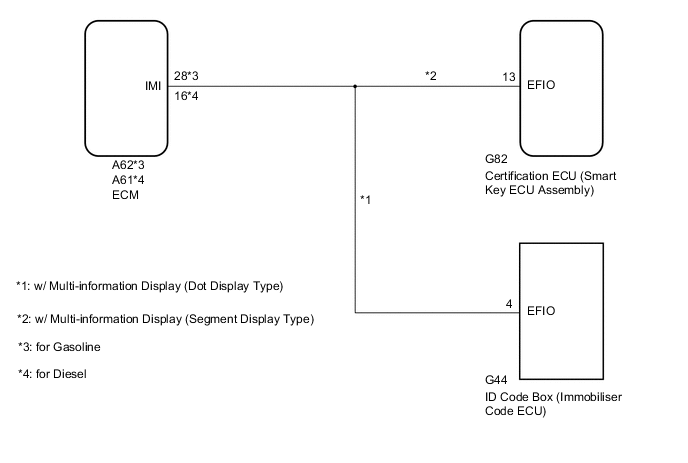
WIRING DIAGRAM
-
1. w/o Blocking System
-
2. w/ Blocking System
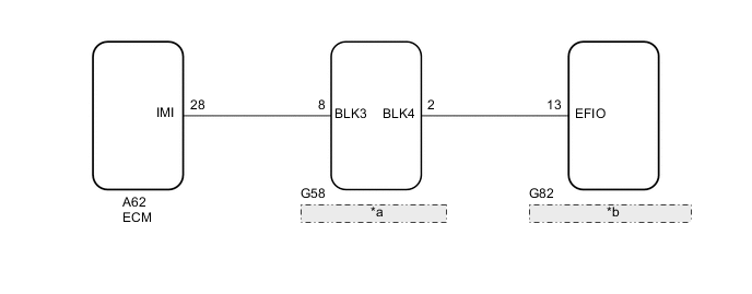
*a Telephone Transceiver Assembly *b Certification ECU (Smart Key ECU Assembly)
CAUTION / NOTICE / HINT
Note
-
When replacing the certification ECU (smart key ECU assembly)*1, ID code box (immobiliser code ECU)*2 or telephone transceiver assembly*3, refer to the Service Bulletin.
-
After repair, confirm that no DTCs are output by performing "DTC Output Confirmation Operation."
-
When the telephone transceiver assembly is replaced, it is necessary to set the contract mode.*3
-
*1: w/ Multi-information Display (Segment Display Type)
-
*2: w/ Multi-information Display (Dot Display Type)
-
*3: w/ Blocking System
Tech Tips
When DTC B279A and the certification ECU (smart key ECU assembly) DTC are output simultaneously, first perform troubleshooting for the certification ECU (smart key ECU assembly) DTC.
PROCEDURE
-
CLEAR DTC
-
Clear the DTCs.
Powertrain > Engine > Clear DTCs
Powertrain > Engine and ECT > Clear DTCsResult Proceed to NEXT
NEXT 
-
-
CHECK FOR DTC
-
Check for DTCs.
Powertrain > Engine > Trouble Codes
Powertrain > Engine and ECT > Trouble CodesTech Tips
If DTCs other than DTC B279A are output, troubleshoot those DTCs first.
Result Proceed to DTC B279A is not output DTC B279A and other DTCs are output
DTC B279A and other DTCs are output 
GO TO DIAGNOSTIC TROUBLE CODE CHART Click here
DTC B279A is not output
-
-
CHECK CONNECTION OF CONNECTOR
-
Turn the engine switch off.
-
Check that the connectors are properly connected to the ECM, ID code box (immobiliser code ECU)*1, certification ECU (smart key ECU assembly)*2 and telephone transceiver assembly*3.
-
*1: w/ Multi-information Display (Dot Display Type)
-
*2: w/ Multi-information Display (Segment Display Type)
-
*3: w/ Blocking System
OK Connectors are properly connected. Result Proceed to OK (w/o Blocking System) OK (w/ Blocking System) NG -
OK (w/ Blocking System) 
CHECK HARNESS AND CONNECTOR (ECM - TELEPHONE TRANSCEIVER ASSEMBLY) Click here
NG
CONNECT CONNECTORS PROPERLY
OK (w/o Blocking System)
-
-
CHECK HARNESS AND CONNECTOR (ID CODE BOX [IMMOBILISER CODE ECU] OR CERTIFICATION ECU [SMART KEY ECU ASSEMBLY] - ECM)
-
*1: w/ Multi-information Display (Dot Display Type)
-
*2: w/ Multi-information Display (Segment Display Type)
-
*3: for Gasoline
-
*4: for Diesel
-
Disconnect the G44 ID code box (immobiliser code ECU) connector.*1
-
Disconnect the G82 certification ECU (smart key ECU assembly) connector.*2
-
Disconnect the A62*3 or A61*4 ECM connector.
-
Measure the resistance according to the value(s) in the table below.
Standard Resistance for Gasoline Tester Connection Condition Specified Condition G44-4 (EFIO) - A62-28 (IMI)*1 Always Below 1 Ω G82-13 (EFIO) - A62-28 (IMI)*2 A62-28 (IMI) - Body ground Always 10 kΩ or higher G44-4 (EFIO) - Body ground*1 Always 10 kΩ or higher G82-13 (EFIO) - Body ground*2 Always 10 kΩ or higher for Diesel Tester Connection Condition Specified Condition G44-4 (EFIO) - A61-16 (IMI)*1 Always Below 1 Ω G82-13 (EFIO) - A61-16 (IMI)*2 A61-16 (IMI) - Body ground Always 10 kΩ or higher G44-4 (EFIO) - Body ground*1 Always 10 kΩ or higher G82-13 (EFIO) - Body ground*2 Always 10 kΩ or higher
-
*1: w/ Multi-information Display (Dot Display Type)
-
*2: w/ Multi-information Display (Segment Display Type)
-
-
Measure the voltage according to the value(s) in the table below.
Standard Voltage for Gasoline Tester Connection Condition Specified Condition A62-28 (IMI) - Body ground Always Below 1 V G44-4 (EFIO) - Body ground*1 Always Below 1 V G82-13 (EFIO) - Body ground*2 Always Below 1 V for Diesel Tester Connection Condition Specified Condition A61-16 (IMI) - Body ground Always Below 1 V G44-4 (EFIO) - Body ground*1 Always Below 1 V G82-13 (EFIO) - Body ground*2 Always Below 1 V
-
*1: w/ Multi-information Display (Dot Display Type)
-
*2: w/ Multi-information Display (Segment Display Type)
Result Proceed to OK (w/ Multi-information Display [Dot Display Type]) OK (w/ Multi-information Display [Segment Display Type]) NG -
OK (w/ Multi-information Display [Segment Display Type])
REPLACE CERTIFICATION ECU (SMART KEY ECU ASSEMBLY) Click here
NG
REPAIR OR REPLACE HARNESS OR CONNECTOR
OK (w/ Multi-information Display [Dot Display Type])
-
-
REPLACE ID CODE BOX (IMMOBILISER CODE ECU)
-
Replace the ID code box (immobiliser code ECU) with a new one.
Tech Tips
Refer to the Service Bulletin.
Result Proceed to NEXT
NEXT
-
-
REGISTER RECOGNITION CODES
-
Register the recognition codes in the ECUs.
Tech Tips
Refer to the Service Bulletin.
Result Proceed to NEXT
NEXT
-
-
REGISTER ECU COMMUNICATION ID
-
Register the ECU communication ID.
Tech Tips
Refer to the Service Bulletin.
Result Proceed to NEXT
NEXT
-
-
CLEAR DTC
-
Clear the DTCs.
Powertrain > Engine > Clear DTCs
Powertrain > Engine and ECT > Clear DTCsResult Proceed to NEXT
NEXT
-
-
CHECK FOR DTC
-
Check for DTCs.
Powertrain > Engine > Trouble Codes
Powertrain > Engine and ECT > Trouble CodesTech Tips
Before checking for DTCs perform the "DTC Output Confirmation Operation" procedure.
Result Proceed to DTC B279A is not output DTC B279A is output (for 2AR-FE) DTC B279A is output (for 3ZR-FAE) DTC B279A is output (for 3ZR-FE) DTC B279A is output (for 1AD-FTV) DTC B279A is output (for 2AD-FTV) DTC B279A is output (for 2AD-FHV)
DTC B279A is not output
END (ID CODE BOX [IMMOBILISER CODE ECU] WAS DEFECTIVE)
DTC B279A is output (for 2AR-FE)
REPLACE ECM Click here
DTC B279A is output (for 3ZR-FAE)
REPLACE ECM Click here
DTC B279A is output (for 3ZR-FE)
REPLACE ECM Click here
DTC B279A is output (for 1AD-FTV)
REPLACE ECM Click here
DTC B279A is output (for 2AD-FTV)
REPLACE ECM Click here
DTC B279A is output (for 2AD-FHV)
REPLACE ECM Click here
-
-
REPLACE CERTIFICATION ECU (SMART KEY ECU ASSEMBLY)
-
Replace the certification ECU (smart key ECU assembly) with a new one.
Tech Tips
Refer to the Service Bulletin.
Result Proceed to NEXT
NEXT
-
-
REGISTER RECOGNITION CODES
-
Register the recognition codes in the ECUs.
Tech Tips
Refer to the Service Bulletin.
Result Proceed to NEXT
NEXT
-
-
REGISTER ECU COMMUNICATION ID
-
Register the ECU communication ID.
Tech Tips
Refer to the Service Bulletin.
Result Proceed to NEXT
NEXT
-
-
CLEAR DTC
-
Clear the DTCs.
Powertrain > Engine > Clear DTCs
Powertrain > Engine and ECT > Clear DTCsResult Proceed to NEXT
NEXT
-
-
CHECK FOR DTC
-
Check for DTCs.
Powertrain > Engine > Trouble Codes
Powertrain > Engine and ECT > Trouble CodesTech Tips
Before checking for DTCs perform the "DTC Output Confirmation Operation" procedure.
Result Proceed to DTC B279A is not output DTC B279A is output (for 2AR-FE) DTC B279A is output (for 3ZR-FAE) DTC B279A is output (for 3ZR-FE) DTC B279A is output (for 1AD-FTV) DTC B279A is output (for 2AD-FTV) DTC B279A is output (for 2AD-FHV)
DTC B279A is not output
END (CERTIFICATION ECU [SMART KEY ECU ASSEMBLY] WAS DEFECTIVE)
DTC B279A is output (for 2AR-FE)
REPLACE ECM Click here
DTC B279A is output (for 3ZR-FAE)
REPLACE ECM Click here
DTC B279A is output (for 3ZR-FE)
REPLACE ECM Click here
DTC B279A is output (for 1AD-FTV)
REPLACE ECM Click here
DTC B279A is output (for 2AD-FTV)
REPLACE ECM Click here
DTC B279A is output (for 2AD-FHV)
REPLACE ECM Click here
-
-
CHECK HARNESS AND CONNECTOR (ECM - TELEPHONE TRANSCEIVER ASSEMBLY)
-
Disconnect the A62 ECM connector.
-
Disconnect the G58 telephone transceiver assembly connector.
-
Measure the resistance according to the value(s) in the table below.
Standard Resistance Tester Connection Condition Specified Condition A62-28 (IMI) - G58-8 (BLK3) Always Below 1 Ω A62-28 (IMI) - Body ground Always 10 kΩ or higher G58-8 (BLK3) - Body ground Always 10 kΩ or higher -
Measure the voltage according to the value(s) in the table below.
Standard Voltage Tester Connection Condition Specified Condition A62-28 (IMI) - Body ground Always Below 1 V G58-8 (BLK3) - Body ground Always Below 1 V Result Proceed to OK NG
NG
REPAIR OR REPLACE HARNESS OR CONNECTOR
OK
-
-
CHECK HARNESS AND CONNECTOR (CERTIFICATION ECU [SMART KEY ECU ASSEMBLY] - TELEPHONE TRANSCEIVER ASSEMBLY)
-
Disconnect the G82 certification ECU (smart key ECU assembly) connector.
-
Disconnect the G58 telephone transceiver assembly connector.
-
Measure the resistance according to the value(s) in the table below.
Standard Resistance Tester Connection Condition Specified Condition G82-13 (EFIO) - G58-2 (BLK4) Always Below 1 Ω G82-13 (EFIO) - Body ground Always 10 kΩ or higher G58-2 (BLK4) - Body ground Always 10 kΩ or higher -
Measure the voltage according to the value(s) in the table below.
Standard Voltage Tester Connection Condition Specified Condition G82-13 (EFIO) - Body ground Always Below 1 V G58-2 (BLK4) - Body ground Always Below 1 V Result Proceed to OK NG
NG
REPAIR OR REPLACE HARNESS OR CONNECTOR
OK
-
-
REPLACE TELEPHONE TRANSCEIVER ASSEMBLY
-
Temporarily replace the telephone transceiver assembly with a new or known good one.
Tech Tips
Refer to the Service Bulletin.
Result Proceed to NEXT
NEXT
-
-
REGISTER ECU COMMUNICATION ID
-
Register the ECU communication ID.
Tech Tips
Refer to the Service Bulletin.
Result Proceed to NEXT
NEXT
-
-
CLEAR DTC
-
Clear the DTCs.
Powertrain > Engine and ECT > Clear DTCsResult Proceed to NEXT
NEXT
-
-
CHECK FOR DTC
-
Check for DTCs.
Powertrain > Engine and ECT > Trouble CodesTech Tips
Before checking for DTCs perform the "DTC Output Confirmation Operation" procedure.
Result Proceed to DTC B279A is not output DTC B279A is output
DTC B279A is not output
END (TELEPHONE TRANSCEIVER ASSEMBLY WAS DEFECTIVE)
DTC B279A is output
GO TO STEP 10 Click here
-