VEHICLE STABILITY CONTROL SYSTEM VSC Buzzer Circuit
DESCRIPTION
The skid control ECU (brake actuator assembly) is connected to the combination meter assembly via CAN communication.
The combination meter assembly has a built-in buzzer.
WIRING DIAGRAM
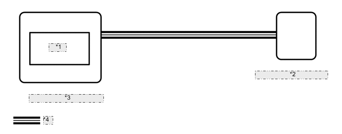
| *1 | Buzzer |
| *2 | Skid Control ECU (Brake Actuator Assembly) |
| *3 | Combination Meter Assembly |
| *4 | CAN Communication Line |
CAUTION / NOTICE / HINT
Note
When replacing the skid control ECU (brake actuator assembly), perform zero point calibration.
PROCEDURE
-
CHECK CAN COMMUNICATION SYSTEM
-
Check if CAN communication system DTCs are output.
for LHD: Click here
for RHD: Click here
Result Proceed to DTC is not output DTC is output (for LHD) DTC is output (for RHD)
DTC is output (for LHD) 
CHECK CAN COMMUNICATION SYSTEM Click here
DTC is output (for RHD)
CHECK CAN COMMUNICATION SYSTEM Click here
DTC is not output 
-
-
PERFORM ACTIVE TEST USING GTS (BUZZER)
-
Turn the ignition switch off.
-
Connect the GTS to the DLC3.
-
Turn the ignition switch to ON.
-
Turn the GTS on.
-
Enter the following menus: Chassis / ABS/VSC/TRC / Active Test.
-
According to the display on the GTS, perform the Active Test.
Chassis > ABS/VSC/TRC > Active TestTester Display Measurement Item Control Range Diagnostic Note Buzzer meter buzzer ON/OFF Buzzer can be heard
Vehicle condition: Vehicle stopped
-
When performing the Buzzer Active Test, check Buzzer in the Data List.
Chassis > ABS/VSC/TRC > Data ListTester Display Measurement Item Range Normal Condition Diagnostic Note Buzzer Meter buzzer ON or OFF OFF: Buzzer off
ON: Buzzer on
The combination meter assembly has a built-in buzzer.
Chassis > ABS/VSC/TRC > Active TestActive Test Display Buzzer Data List Display Buzzer Result Result Proceed to Buzzer in the Data List does not change using the Active Test A Buzzer in the Data List turns ON/OFF using the Active Test B
A
REPLACE BRAKE ACTUATOR ASSEMBLY Click here
B
-
-
INSPECT COMBINATION METER ASSEMBLY
-
Inspect the combination meter.
Result Result OK NG
OK
REPLACE BRAKE ACTUATOR ASSEMBLY Click here
NG
REPLACE COMBINATION METER ASSEMBLY Click here
-