TIRE PRESSURE WARNING SYSTEM TC and CG Terminal Circuit
DESCRIPTION
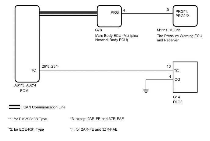
DTC output mode is set by connecting terminals 13 (TC) and 4 (CG) of the DLC3. The DTCs are indicated by the blinking of the tire pressure warning light.
WIRING DIAGRAM
PROCEDURE
-
CHECK CAN COMMUNICATION SYSTEM
-
Check the CAN communication system.
for LHD: Click here
for RHD: Click here
CAN Bus CheckOK The CAN communication system is normal. Result Proceed to OK NG
NG 
GO TO CAN COMMUNICATION SYSTEM for LHD: Click here
GO TO CAN COMMUNICATION SYSTEM for RHD: Click hereOK 
-
-
CHECK DTC OUTPUT (C2179/79)
-
Clear the DTCs.
Chassis > Tire Pressure Monitor > Clear DTCs -
Turn the ignition switch off.
-
Turn the ignition switch to ON.
-
Check for DTCs.
Chassis > Tire Pressure Monitor > Trouble CodesOK DTC C2179/79 is not output. Result Proceed to OK NG
NG
GO TO DTC C2179/79 Click here
OK
-
-
CHECK HARNESS AND CONNECTOR (TC of DLC3 - ECM)
-
Disconnect the ECM A61*1 or A62*2 connector.
-
*1: except 2AR-FE and 3ZR-FAE
-
*2: for 2AR-FE and 3ZR-FAE
-
-
Measure the resistance according to the value(s) in the table below.
Standard Resistance except 2AR-FE and 3ZR-FAE Tester Connection Condition Specified Condition G14-13 (TC) - A61-26 (TC) Always Below 1 Ω for 2AR-FE and 3ZR-FAE Tester Connection Condition Specified Condition G14-13 (TC) - A62-23 (TC) Always Below 1 Ω Result Proceed to OK NG
NG
REPAIR OR REPLACE HARNESS OR CONNECTOR
OK
-
-
CHECK HARNESS AND CONNECTOR (CG of DLC3 - BODY GROUND)
-
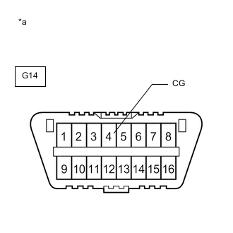
*a Front view of DLC3 Measure the resistance according to the value(s) in the table below.
Standard Resistance Tester Connection Condition Specified Condition G14-4 (CG) - Body ground Always Below 1 Ω Result Proceed to OK NG
NG
REPAIR OR REPLACE HARNESS OR CONNECTOR
OK
-
-
INSPECT DLC3 (TC VOLTAGE)
-
Connect the ECM A61*1 or A62*2 connector.
-
*1: except 2AR-FE and 3ZR-FAE
-
*2: for 2AR-FE and 3ZR-FAE
-
-
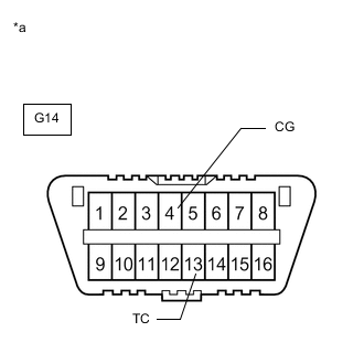
*a Front view of DLC3 Measure the voltage according to the value(s) in the table below.
Standard Voltage Tester Connection Switch Condition Specified Condition G14-13 (TC) - G14-4 (CG) Ignition switch ON 11 to 14 V Result Proceed to OK NG
OK
PROCEED TO NEXT SUSPECTED AREA SHOWN IN PROBLEM SYMPTOMS TABLE Click here
NG
REPLACE ECM for 1AD-FTV: Click here
REPLACE ECM for 2AD-FHV: Click here
REPLACE ECM for 2AD-FTV: Click here
REPLACE ECM for 2AR-FE: Click here
REPLACE ECM for 3ZR-FAE: Click here -