FRONT DRIVE SHAFT ASSEMBLY(for 4WD/AWD) INSTALLATION

PROCEDURE
-
INSTALL FRONT DRIVE SHAFT HOLE SNAP RING LH
-
Install a new front drive shaft hole snap ring LH.
-
-
INSTALL FRONT DRIVE SHAFT ASSEMBLY LH
-
Coat the spline of the inboard joint shaft assembly with MP grease.
-
Set the front drive shaft hole snap ring LH with the opening side facing down.
-
Align the splines and tap in the front drive shaft assembly with a brass bar and hammer.
Note
-
Using MP grease, set the front drive shaft hole snap ring in the groove with the opening facing downwards and centered radially.
-
Be careful not to damage the oil seal, front axle inboard joint boot and front drive shaft dust cover.
-
-
-
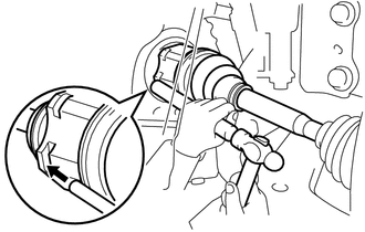
INSTALL FRONT DRIVE SHAFT ASSEMBLY RH
-
Install a new drive shaft bearing bracket hole snap ring to the front drive shaft assembly RH.
-
Align the shaft splines and securely install the front drive shaft assembly RH.
Note
-
Be careful not to damage the transaxle case oil seal, inboard joint boot and drive shaft dust cover.
-
When inserting the front drive shaft assembly RH, keep it level.
-
-
Install the drive shaft bearing bracket hole snap ring and a new bolt.
- Torque:
- 32 N*m { 326 kgf*cm, 24 ft.*lbf }
-
-
CONNECT STEERING KNUCKLE WITH AXLE HUB LH
-
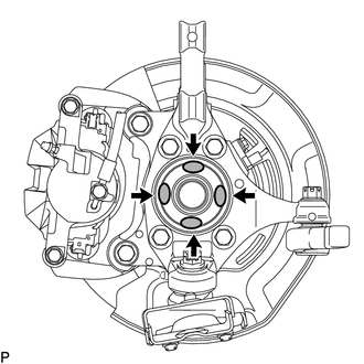
Apply MP grease to the entire contact surface between the front drive shaft assembly and axle hub bearing surface or only apply 0.1 to 0.3 g (0.00353 to 0.0105 oz.) of MP grease to the 4 areas on the axle hub bearing shown in the illustration.
-
Align the matchmarks and connect the steering knuckle with axle hub LH.
-
Attach the 2 guides and install the bolt.
- Torque:
- 18.5 N*m { 189 kgf*cm, 14 ft.*lbf }
-
-
CONNECT STEERING KNUCKLE WITH AXLE HUB RH
Tech Tips
Use the same procedure described for the LH side.
-
CONNECT FRONT LOWER NO. 1 SUSPENSION ARM SUB-ASSEMBLY LH
-
CONNECT FRONT LOWER NO. 1 SUSPENSION ARM SUB-ASSEMBLY RH
Tech Tips
Use the same procedure described for the LH side.
-
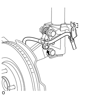
INSTALL FRONT STABILIZER LINK ASSEMBLY LH
-
INSTALL FRONT STABILIZER LINK ASSEMBLY RH
Tech Tips
Use the same procedure described for the LH side.
-
CONNECT FRONT SPEED SENSOR LH
-
CONNECT FRONT SPEED SENSOR RH
Tech Tips
Use the same procedure described for the LH side.
-
INSTALL FRONT AXLE SHAFT NUT LH
-
INSTALL FRONT AXLE SHAFT NUT RH
Tech Tips
Use the same procedure described for the LH side.
-
ADD AUTOMATIC TRANSAXLE FLUID
-
for U660F: Click here
-
for U760F: Click here
-
-
ADD MANUAL TRANSAXLE OIL
-
for EA64F: Click here
-
for EB61F: Click here
-
for EB63F: Click here
-
-
ADD CONTINUOUSLY VARIABLE TRANSAXLE FLUID
-
ADD TRANSFER OIL
-
INSPECT FOR OIL LEAK
-
INSTALL REAR ENGINE UNDER COVER RH
-
for 2AD-FTV, 2AD-FHV: Click here
-
for 2AR-FE: Click here
-
for 3ZR-FE: Click here
-
for 3ZR-FAE: Click here
-
-
INSTALL REAR ENGINE UNDER COVER LH
-
for 2AD-FTV, 2AD-FHV: Click here
-
for 2AR-FE: Click here
-
for 3ZR-FE: Click here
-
for 3ZR-FAE: Click here
-
-
INSTALL NO. 1 ENGINE UNDER COVER
-
for 2AD-FTV, 2AD-FHV: Click here
-
for 2AR-FE, 3ZR-FE: Click here
-
for 3ZR-FE: Click here
-
for 3ZR-FAE: Click here
-
-
INSTALL FRONT WHEEL
- Torque:
- 103 N*m { 1050 kgf*cm, 76 ft.*lbf }
-
CHECK SPEED SENSOR SIGNAL
-
w/ VSC: Click here
-
w/o VSC: Click here
-
-
INSPECT AND ADJUST FRONT WHEEL ALIGNMENT