DYNAMIC TORQUE CONTROL 4WD/AWD SYSTEM 4WD Warning Light Remains ON
DESCRIPTION
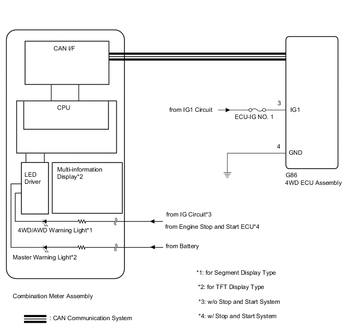
The 4WD ECU assembly is connected to the combination meter assembly via the CAN communication system.
-
for Segment Display Type:
If the 4WD ECU assembly stores any DTCs which are related to the dynamic torque control 4WD/AWD system , the 4WD/AWD warning light comes on in the combination meter assembly.
-
for TFT Display Type:
If the 4WD ECU assembly stores any DTCs which are related to the dynamic torque control 4WD/AWD system , the master warning light comes on and the warning message is displayed on the multi-information display in the combination meter assembly.
WIRING DIAGRAM
CAUTION / NOTICE / HINT
Note
Inspect the fuses for circuits related to this system before performing the following inspection procedure.
PROCEDURE
-
CHECK FOR DTC (CAN COMMUNICATION SYSTEM AND DYNAMIC TORQUE CONTROL 4WD/AWD SYSTEM)
-
Check if CAN communication system DTCs are output.
for LHD with Central Gateway ECU: Click here
for RHD with Central Gateway ECU: Click here
for LHD without Central Gateway ECU: Click here
for RHD without Central Gateway ECU: Click here
-
Check if the dynamic torque control 4WD/AWD system DTC is output.
Click here
Chassis > Four Wheel Drive > Trouble CodesResult Result Proceed to Neither CAN communication system DTC nor dynamic torque control 4WD/AWD system DTC is output A CAN communication DTC is output (for LHD with Central Gateway ECU) B CAN communication DTC is output (for RHD with Central Gateway ECU) C CAN communication DTC is output (for LHD without Central Gateway ECU) D CAN communication DTC is output (for RHD without Central Gateway ECU) E Dynamic torque control 4WD/AWD system DTC is output F Tech Tips
When DTCs indicating a CAN communication system malfunction are output, repair the CAN communication system before repairing each corresponding sensor.
B 
GO TO CAN COMMUNICATION SYSTEM (HOW TO PROCEED WITH TROUBLESHOOTING) Click here
C
GO TO CAN COMMUNICATION SYSTEM (HOW TO PROCEED WITH TROUBLESHOOTING) Click here
D
GO TO CAN COMMUNICATION SYSTEM (HOW TO PROCEED WITH TROUBLESHOOTING) Click here
E
GO TO CAN COMMUNICATION SYSTEM (HOW TO PROCEED WITH TROUBLESHOOTING) Click here
F
REPAIR CIRCUIT INDICATED BY OUTPUT CODE (DYNAMIC TORQUE CONTROL 4WD/AWD SYSTEM) Click here
A 
-
-
CHECK IF 4WD ECU ASSEMBLY CONNECTOR IS SECURELY CONNECTED
-
Check if the 4WD ECU assembly connector is securely connected.
OK The connector is securely connected. Result Proceed to OK NG
NG
CONNECT CONNECTOR TO ECU CORRECTLY
OK
-
-
INSPECT BATTERY
-
Check the battery voltage.
Standard voltage 11 to 14 V Result Proceed to OK NG (for 2AR-FE) NG (for 2AD-FHV) NG (for 2AD-FTV) NG (for 3ZR-FAE) NG (for 3ZR-FE)
NG (for 2AR-FE)
CHECK CHARGING SYSTEM Click here
NG (for 2AD-FHV)
CHECK CHARGING SYSTEM Click here
NG (for 2AD-FTV)
CHECK CHARGING SYSTEM Click here
NG (for 3ZR-FAE)
CHECK CHARGING SYSTEM Click here
NG (for 3ZR-FE)
CHECK CHARGING SYSTEM Click here
OK
-
-
CHECK HARNESS AND CONNECTOR (IG1 TERMINAL)
-
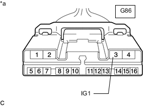
*a Front view of wire harness connector
(to 4WD ECU Assembly)
Disconnect the 4WD ECU assembly connector.
-
Turn the ignition switch to ON.
-
Measure the voltage according to the value(s) in the table below.
Standard Voltage Tester Connection Switch Condition Specified Condition G86-3 (IG1) - Body ground Ignition switch ON 11 to 14 V Result Proceed to OK NG
NG
REPAIR OR REPLACE HARNESS OR CONNECTOR
OK
-
-
CHECK HARNESS AND CONNECTOR (GND TERMINAL)
-
Turn the ignition switch off.
-
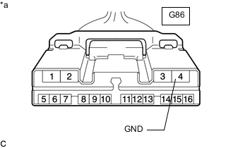
*a Front view of wire harness connector
(to 4WD ECU Assembly)
Measure the resistance according to the value(s) in the table below.
Standard Resistance Tester Connection Condition Specified Condition G86-4 (GND) - Body ground Always Below 1 Ω Result Proceed to OK NG
NG
REPAIR OR REPLACE HARNESS OR CONNECTOR
OK
-
-
READ VALUE USING GTS (4WD WARNING LIGHT)
-
Warm up the engine.
-
Turn the ignition switch off.
-
Connect the GTS the DLC3.
-
Turn the ignition switch to ON.
-
Turn the GTS on.
-
Enter the following menus: Chassis / Four Wheel Drive / Data List.
-
According to the display on the GTS, read the Data List.
Chassis > Four Wheel Drive > Data ListTester Display Measurement Item Range Normal Condition Diagnostic Note 4WD Warning Light 4WD/AWD warning Light*1
4WD/AWD warning (multi-information display)*2
OFF or ON OFF: Warning light off*1
OFF: Warning off*2
ON: Warning light on*1
ON: Warning on*2
-
-
*1: for Segment Display Type
-
*2: for TFT Display Type
Chassis > Four Wheel Drive > Data ListTester Display 4WD Warning Light -
-
Check the GTS diplay condition of the 4WD/AWD warning light.
Result Proceed to Display of the Data List remains OFF Display of the Data List remains ON
Display of the Data List remains OFF
GO TO METER / GAUGE SYSTEM (HOW TO PROCEED WITH TROUBLESHOOTING) Click here
Display of the Data List remains ON
REPLACE 4WD ECU ASSEMBLY Click here
-