CONTINUOUSLY VARIABLE TRANSAXLE SYSTEM, Diagnostic DTC:P1585
| DTC Code | DTC Name |
|---|---|
| P1585 | Acceleration Sensor Circuit |
DESCRIPTION
The ECM determines the vehicle inclination based on a signal from the yaw rate and acceleration sensor (airbag sensor assembly).
| DTC No. | Detection Item | DTC Detection Condition | Trouble Area | MIL | Memory |
|---|---|---|---|---|---|
| P1585 | Acceleration Sensor Circuit | 1. Diagnosis Condition 2. Malfunction Status 3. Malfunction Time 4. Other
|
|
- | DTC stored |
WIRING DIAGRAM
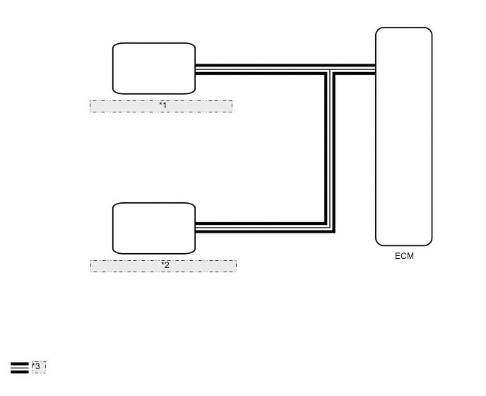
| *1 | Skid Control ECU (Brake Actuator Assembly) |
| *2 | Yaw Rate and Acceleration Sensor (Airbag Sensor Assembly) |
| *3 | CAN Communication Line |
CAUTION / NOTICE / HINT
Note
-
Perform initialization when parts related to the continuously variable transaxle are replaced.
-
Check that no DTCs are stored after performing initialization.
Tech Tips
If a CAN communication DTC is output, perform troubleshooting for that DTC first.
PROCEDURE
-
CHECK DTC OUTPUT (CAN COMMUNICATION SYSTEM)
-
Check for DTCs of the CAN communication system.
-
for LHD with Central Gateway ECU:
-
for RHD with Central Gateway ECU:
-
for LHD without Central Gateway ECU:
-
for RHD without Central Gateway ECU:
Result Proceed to DTCs are not output DTCs are output -
DTCs are output 
GO TO CAN COMMUNICATION SYSTEM (DIAGNOSIS SYSTEM) for LHD with Central Gateway ECU: Click here for RHD with Central Gateway ECU: Click here for LHD without Central Gateway ECU: Click here for RHD without Central Gateway ECU: Click here
DTCs are not output 
-
-
READ VALUE USING GTS (G SENSOR)
-
Connect the GTS to the DLC3.
-
Turn the ignition switch to ON.
-
Turn the GTS on.
-
Enter the following menus: Powertrain / Engine and ECT / Data List.
Powertrain > Engine and ECT > Data ListTester Display G Sensor
Powertrain > Engine and ECT > Data ListTester Display Measurement Item Range Normal Condition Diagnostic Note G Sensor Converted output voltage of deceleration sensor min.: 0 V
max.: 79.998 V
Displays converted voltage of deceleration sensor
-
Vehicle on level ground: 2.31 V to 2.69 V
-
Decelerating: 1.88 V to 2.5 V
-
Accelerating: 2.5 V to 3.11 V
-
G sensor malfunction: Set to 1.87 V
-
Communication malfunction: Set to 1.87 V
- -
-
In accordance with the display on the GTS, read the Data List.
Result Result Proceed to Data displayed is as specified under Normal Condition A Data displayed is not as specified under Normal Condition B
A
REPLACE SKID CONTROL ECU (BRAKE ACTUATOR ASSEMBLY) Click here
B
-
-
REPLACE YAW RATE AND ACCELERATION SENSOR (AIRBAG SENSOR ASSEMBLY)
-
Replace the yaw rate and acceleration sensor (airbag sensor assembly).
Result Proceed to NEXT
NEXT
PERFORM INITIALIZATION Click here
-