ENGINE ASSEMBLY REMOVAL

CAUTION / NOTICE / HINT
CAUTION:
As the engine assembly with transaxle is extremely heavy, the engine lifter may suddenly drop if the instructions listed in the repair manual are not followed. Therefore, always follow the instructions listed in the repair manual when performing this procedure.
PROCEDURE
-
PLACE FRONT WHEELS FACING STRAIGHT AHEAD
-
RECOVER REFRIGERANT FROM REFRIGERATION SYSTEM
-
PRECAUTION
Note
After turning the ignition switch off, waiting time may be required before disconnecting the cable from the battery terminal. Therefore, make sure to read the disconnecting the cable from the battery terminal notice before proceeding with work.
-
DISCONNECT CABLE FROM NEGATIVE BATTERY TERMINAL
Note
When disconnecting the cable, some systems need to be initialized after the cable is reconnected.
-
DISCONNECT CABLE FROM POSITIVE BATTERY TERMINAL
-
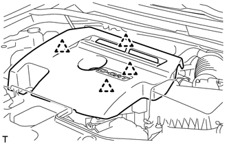
REMOVE NO. 1 ENGINE COVER
-
Detach the 4 clips and remove the No. 1 engine cover.
Note
Attempting to disengage both front and rear clips at the same time may cause the No. 1 engine cover to break.
-
-
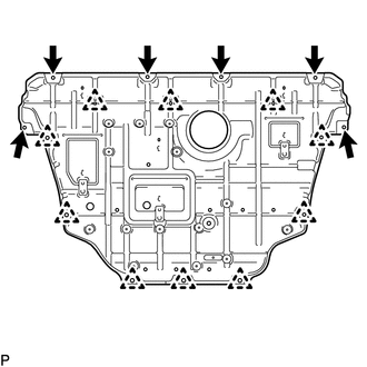
REMOVE NO. 1 ENGINE UNDER COVER
-
Remove the 4 bolts and 2 screws.
-
Remove the 10 clips and No. 1 engine under cover.
-
-
REMOVE FRONT FLOOR COVER
-
REMOVE NO. 2 ENGINE UNDER COVER
-
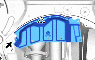
Remove the bolt, clip and No. 2 engine under cover.
-
-
REMOVE FRONT FLOOR COVER RH
-
Loosen the 3 nuts and remove the 3 clips and front floor cover RH.
-
-
REMOVE REAR ENGINE UNDER COVER RH
-
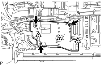
REMOVE REAR ENGINE UNDER COVER LH
-
Remove the 2 clips and rear engine under cover LH.
-
-
DRAIN ENGINE COOLANT
-
DRAIN ENGINE OIL
-
DRAIN MANUAL TRANSAXLE OIL (for Manual Transaxle)
-
DRAIN AUTOMATIC TRANSAXLE FLUID (for Automatic Transaxle)
-
DRAIN TRANSFER OIL
-
REMOVE FRONT BUMPER COVER (for Automatic Transaxle)
-
REMOVE FRONT EXHAUST PIPE ASSEMBLY
-
REMOVE PROPELLER SHAFT WITH CENTER BEARING ASSEMBLY
-
REMOVE DIFFERENTIAL PRESSURE SENSOR ASSEMBLY
-
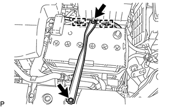
REMOVE BATTERY CLAMP SUB-ASSEMBLY
-
Remove the bolt and loosen the nut.
-
Detach the 2 wire harness clamps.
-
Detach the hook of the battery clamp sub-assembly from the front battery bracket, and then remove the battery clamp sub-assembly.
-
-
REMOVE BATTERY INSULATOR
-
REMOVE BATTERY
-
REMOVE BATTERY TRAY
-
REMOVE FRONT BATTERY BRACKET
-
Detach the 2 wire harness clamps.
-
Remove the 4 bolts and front battery bracket.
-
-
REMOVE BATTERY BRACKET REINFORCEMENT
-
Remove the 2 bolts and battery bracket reinforcement.
-
-
REMOVE RADIATOR ASSEMBLY (for Automatic Transaxle)
-
DISCONNECT NO. 2 VACUUM TRANSMITTING HOSE ASSEMBLY
-
REMOVE NO. 3 AIR HOSE
-
REMOVE AIR CLEANER CAP SUB-ASSEMBLY
-
Disconnect the PCV hose.
-
Loosen the hose clamp and disconnect the air cleaner hose.
-
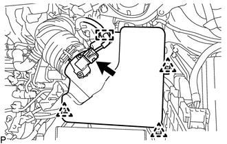
Disconnect the mass air flow meter connector and wire harness clamp.
-
Detach the 3 clips and remove the air cleaner cap sub-assembly.
-
-
REMOVE AIR CLEANER FILTER ELEMENT SUB-ASSEMBLY
-
REMOVE AIR CLEANER CASE
-
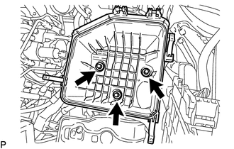
Remove the 3 bolts and air cleaner case.
-
-
REMOVE AIR CLEANER SUPPORT
-
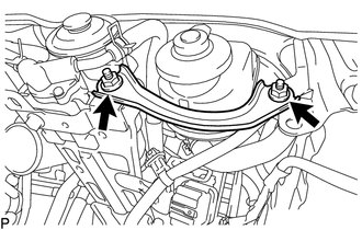
Remove the 2 nuts and air cleaner support.
-
-
REMOVE FUEL FILTER ASSEMBLY
-
Slide the 2 clips and disconnect the 2 fuel hoses.
-
Remove the bolt and fuel filter assembly.
-
-
REMOVE AIR CLEANER BRACKET
-
Disconnect the glow plug relay and level warning switch connector.
-
Detach the 3 wire harness clamps.
-
Disconnect the 2 fuel hoses from the air cleaner bracket.
-
Remove the 3 bolts and air cleaner bracket.
-
-
REMOVE ECM
-
DISCONNECT HOSES AND CONNECTORS
-
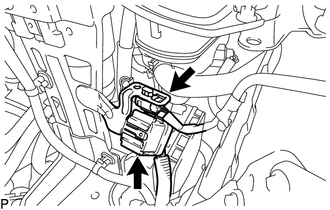
Remove the engine room relay block and junction block cover.
-
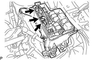
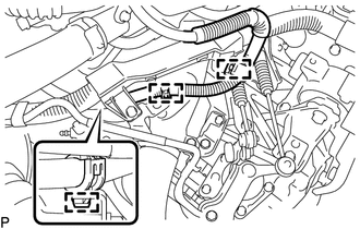
Disconnect the 3 connectors from the engine room No. 1 relay block.
-
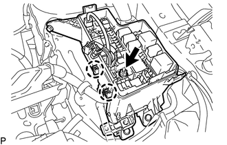
Remove the nut.
-
Detach the 2 claws and disconnect the engine wire.
-
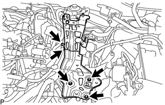
Remove the bolt and disconnect the engine wire cover clamp and engine wire harness clamp.
-
Remove the nut and disconnect the starter wire.
-
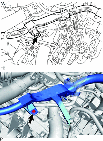
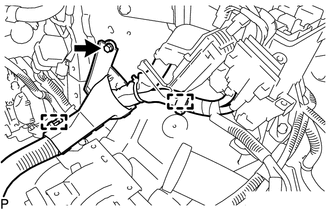
*A for Manual Transaxle *B for Automatic Transaxle Remove the bolt from the wire harness clamp bracket.
-
for Manual Transaxle:
Detach the clamp, remove the bolt and disconnect the ground cable from the manual transaxle assembly.
-
for Manual Transaxle:
Detach the wire harness clamp and disconnect the 2 connectors.
-
for Manual Transaxle:
Remove the bolt and disconnect the wire harness from the manual transaxle assembly.
-
for Automatic Transaxle:
Disconnect the transaxle ECM connector and detach the 2 wire harness clamps.
-
for Automatic Transaxle:
Remove the bolt and disconnect the ground cable from the automatic transaxle.
-
for Automatic Transaxle:
Detach the 2 clamps and disconnect the transaxle shift position switch connector.
-
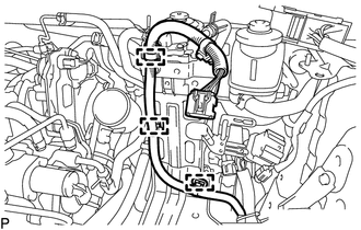
Detach the 3 wire harness clamps from the 3 wire harness brackets.
-
for DPF:
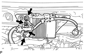
Detach the 2 wire harness clamps and disconnect the 4 injector driver connectors.
-
for DPF:
Remove the 2 nuts and injector driver assembly.
-
for CCo:
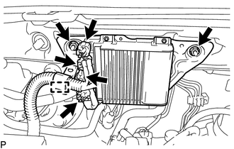
Detach the wire harness clamp and disconnect the 4 injector driver connectors.
-
for CCo:
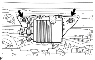
Remove the 2 nuts and injector driver assembly.
-
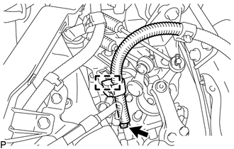
Slide the clip and disconnect the vacuum pump hose from the vacuum pump assembly.
-
-
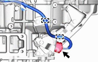
DISCONNECT INLET HEATER WATER HOSE
-
Slide the clamp and disconnect the inlet heater water hose from the cylinder head sub-assembly.
-
-
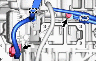
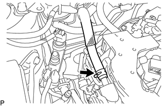
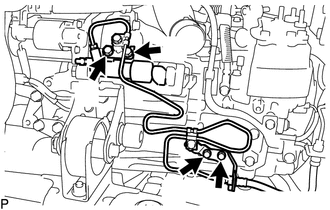
DISCONNECT OUTLET HEATER WATER HOSE
-
Slide the clamp and disconnect the outlet heater water hose from the No. 3 water by-pass pipe.
-
-
DISCONNECT RADIATOR HOSE SUB-ASSEMBLY
-
Slide the clamp and disconnect the radiator hose sub-assembly from the cylinder head sub-assembly.
-
-
REMOVE INTERCOOLER AIR HOSE
-
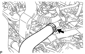
DISCONNECT NO. 2 WATER BY-PASS HOSE
-
Slide the clamp and disconnect the No. 2 water by-pass hose from the No. 4 water by-pass pipe.
-
-
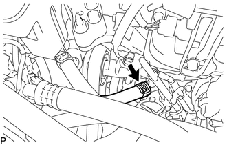
DISCONNECT NO. 2 RADIATOR HOSE
-
Slide the clamp and disconnect the No. 2 radiator hose from the water inlet housing.
-
-
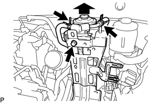
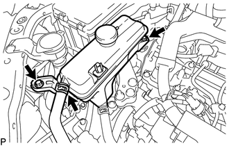
REMOVE RADIATOR RESERVOIR ASSEMBLY
-
Slide the clamp and disconnect the water by-pass hose from the radiator reservoir assembly.
-
Remove the 2 bolts and radiator reservoir assembly.
-
-
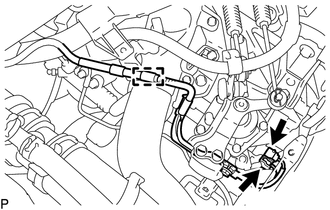
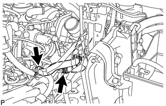
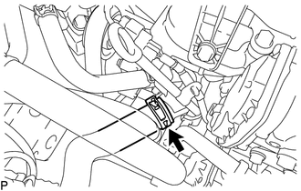
DISCONNECT DISCHARGE HOSE SUB-ASSEMBLY
-
Remove the bolt and disconnect the discharge hose sub-assembly.
-
Remove the O-ring from the discharge hose sub-assembly.
Note
Seal the openings of the disconnected parts using vinyl tape to prevent entry of moisture and foreign matter.
-
Disconnect the cooler compressor connector.
-
-
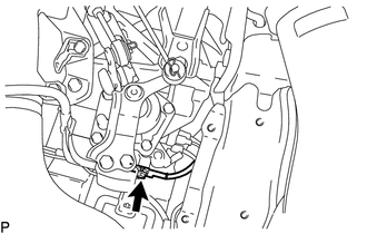
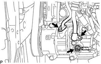
DISCONNECT SUCTION HOSE SUB-ASSEMBLY
-
Remove the bolt and disconnect the suction hose sub-assembly.
-
Remove the O-ring from the suction hose sub-assembly.
Note
Seal the openings of the disconnected parts using vinyl tape to prevent entry of moisture and foreign matter.
-
-
DISCONNECT TRANSMISSION CONTROL CABLE ASSEMBLY (for Manual Transaxle)
-
Remove the 2 pins.
-
Remove the 2 clips and disconnect the 2 transmission control cable assembly from the transmission control cable bracket.
-
-
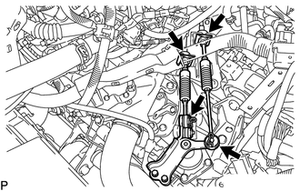
DISCONNECT TRANSMISSION CONTROL CABLE ASSEMBLY (for Automatic Transaxle)
-
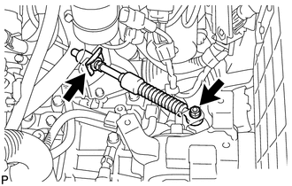
Remove the nut and clip, and disconnect the transmission control cable assembly from the transmission control cable bracket.
-
-
DISCONNECT CLUTCH RELEASE CYLINDER ASSEMBLY (for Manual Transaxle)
-
Remove the 4 bolts and disconnect the clutch release cylinder assembly and clutch flexible hose bracket.
-
-
REMOVE COLUMN HOLE COVER SILENCER SHEET
-
SECURE STEERING WHEEL
-
DISCONNECT NO. 2 STEERING INTERMEDIATE SHAFT ASSEMBLY
-
REMOVE NO. 1 STEERING COLUMN HOLE COVER SUB-ASSEMBLY
-
REMOVE FRONT AXLE SHAFT NUT LH
-
REMOVE FRONT AXLE SHAFT NUT RH
Tech Tips
Perform the same procedure as for the LH side.
-
DISCONNECT FRONT SPEED SENSOR LH
-
DISCONNECT FRONT SPEED SENSOR RH
Tech Tips
Use the same procedure described for the LH side.
-
DISCONNECT FRONT STABILIZER LINK ASSEMBLY LH
-
DISCONNECT FRONT STABILIZER LINK ASSEMBLY RH
Tech Tips
Perform the same procedure as for the LH side.
-
DISCONNECT TIE ROD END SUB-ASSEMBLY LH
-
DISCONNECT TIE ROD END SUB-ASSEMBLY RH
Tech Tips
Use the same procedure described for the LH side.
-
REMOVE FRONT AXLE ASSEMBLY LH
-
REMOVE FRONT AXLE ASSEMBLY RH
Tech Tips
Perform the same procedure as for the LH side.
-
REMOVE FRONT DRIVE SHAFT ASSEMBLY LH
-
REMOVE FRONT DRIVE SHAFT ASSEMBLY RH
-
REMOVE FRONT SUSPENSION MEMBER REINFORCEMENT LH
-
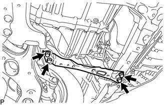
Remove the 4 bolts and front suspension member reinforcement LH.
-
-
REMOVE FRONT SUSPENSION MEMBER REINFORCEMENT RH
-
REMOVE DRIVE PLATE AND TORQUE CONVERTER ASSEMBLY SETTING BOLT (for Automatic Transaxle)
-
REMOVE FUEL HOSE PROTECTOR
-
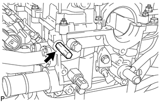
Remove the fuel hose protector from the cylinder head sub-assembly.
-
-
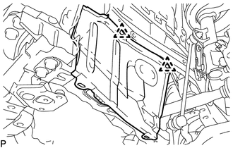
INSTALL ENGINE HANGER
-
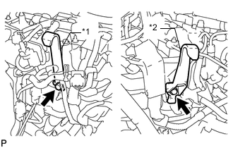
*1 No. 1 Engine Hanger *2 No. 2 Engine Hanger Install the 2 engine hangers with the 2 bolts as shown in the illustration.
- Torque:
- 40 N*m { 408 kgf*cm, 30 ft.*lbf }
Tech Tips
Part No. No. 1 Engine Hanger 12281-26040 No. 2 Engine Hanger 12282-26010 Bolt 91552-81025 or 90105-W0042
-
Insert the claw of the No. 1 engine hanger into the hole of the cylinder head sub-assembly.
-
Fit the fork part of the No. 2 engine hanger onto the rib of the cylinder head sub-assembly.
-
-
REMOVE ENGINE WITH TRANSAXLE
-
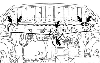
Remove the 6 bolts and disconnect the front crossmember sub-assembly.
-
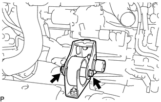
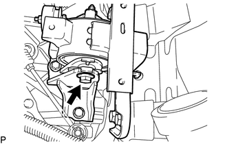
Remove the through bolt, nut and front engine mounting insulator.
-
Set an engine lifter underneath the engine.
Tech Tips
Place the engine on wooden blocks or equivalent so that the engine is level.
-
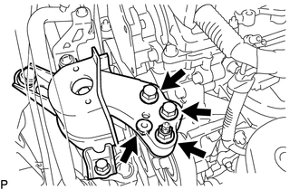
Remove the 2 bolts and 2 nuts and disconnect the engine mounting insulator sub-assembly RH.
-
Remove the bolt and nut and disconnect the engine mounting insulator LH.
-
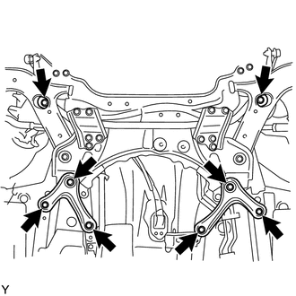
Remove the 6 bolts, front suspension member rear brace RH and front suspension member rear brace LH.
-
Remove the 2 bolts and front suspension member sub-assembly.
-
Carefully remove the engine with transaxle from the vehicle.
Note
-
Make sure that the engine is clear of all wiring and hoses.
-
While lowering the engine from the vehicle, do not allow it to contact the vehicle.
-
-
Attach an engine sling device and hang the engine with a chain block.
-
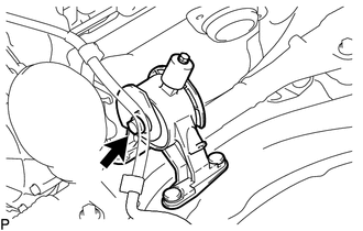
Remove the through bolt and disconnect the rear engine mounting insulator.
-
-
REMOVE NO. 1 AIR TUBE
-
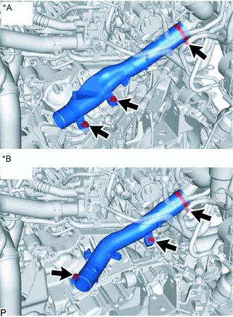
*A for Manual Transaxle *B for Automatic Transaxle Loosen the hose clamp, and remove the 2 bolts and No. 1 air tube.
-
-
REMOVE STARTER ASSEMBLY
-
REMOVE ENGINE WIRE
-
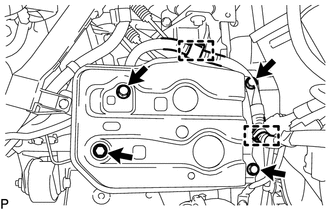
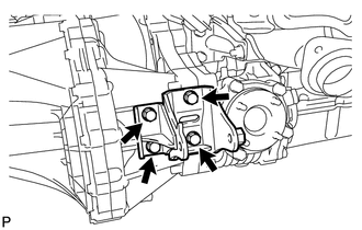
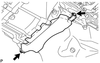
REMOVE FRONT ENGINE MOUNTING BRACKET
-
for Manual Transaxle:
Remove the 3 bolts and front engine mounting bracket.
-
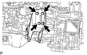
for Automatic Transaxle:
Remove the 4 bolts and front engine mounting bracket.
-
-
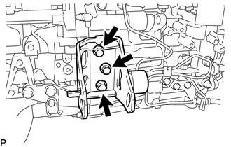
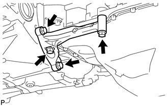
REMOVE REAR ENGINE MOUNTING BRACKET
-
Remove the 4 bolts and rear engine mounting bracket.
-
-
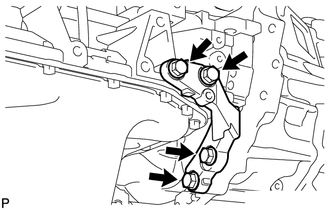
REMOVE ENGINE MOUNTING BRACKET LH
Tech Tips
Perform this procedure only when replacement of the engine mounting bracket LH is necessary.
-
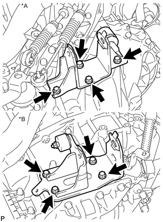
*A for Manual Transaxle *B for Automatic Transaxle Remove the 4 bolts and engine mounting bracket LH from the transaxle assembly.
-
-
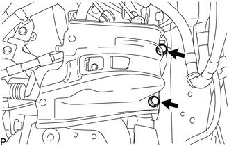
REMOVE OIL PAN INSULATOR
-
Remove the 2 bolts and oil pan insulator.
-
-
REMOVE STIFFENER PLATE RH
-
Remove the 4 bolts and stiffener plate RH.
-
-
REMOVE STIFFENER PLATE LH
-
Remove the 4 bolts and stiffener plate LH.
-
-
FIX ENGINE ASSEMBLY
-
Using wooden blocks or plate lift attachments, set the engine on a flat surface.
Note
-
Place wooden blocks or plate lift attachments so that the engine is level.
-
Never install attachments to the oil pan of the engine assembly or transaxle as doing so may deform the oil pan.
-
Perform this step while supporting the engine assembly using a sling device and chain block.
-
-
-
REMOVE MANUAL TRANSAXLE ASSEMBLY (for Manual Transaxle)
-
REMOVE AUTOMATIC TRANSAXLE ASSEMBLY (for Automatic Transaxle)
-
REMOVE CLUTCH COVER ASSEMBLY (for Manual Transaxle)
-
REMOVE CLUTCH DISC ASSEMBLY (for Manual Transaxle)
-
REMOVE FLYWHEEL WITH DAMPER ASSEMBLY (for Manual Transaxle)
-
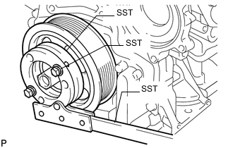
Using SST, hold the crankshaft pulley.
- SST
- 09213-58014 ( 91551-80840 )
- 09330-00021
-
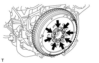
Using a T55 "TORX" socket wrench, remove the 8 bolts and flywheel with damper assembly.
-
-
REMOVE DRIVE PLATE AND RING GEAR SUB-ASSEMBLY (for Automatic Transaxle)
-
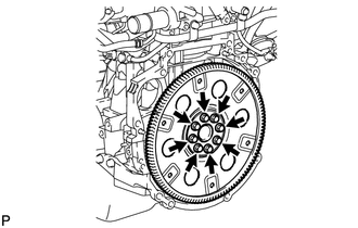
Remove the 8 bolts, rear drive plate spacer, drive plate and ring gear sub-assembly, and front drive plate spacer.
-
-
INSTALL ENGINE TO ENGINE STAND
Note
-
Pay attention to the angle of the sling device as the engine assembly or engine hangers may be damaged or deformed if the angle is incorrect.
-
With the exception of installing the engine assembly to an engine stand or removing the engine assembly from an engine stand, do not perform any work on the engine while it is suspended, as doing so is dangerous.
-
Install the engine to an engine stand, and remove the sling device and chain block from the engine.
-
Remove the 2 bolts, No. 1 engine hanger and No. 2 engine hanger.
-
-
REMOVE REAR ENGINE MOUNTING INSULATOR
Tech Tips
Perform this procedure only when replacement of the rear engine mounting insulator is necessary.
-
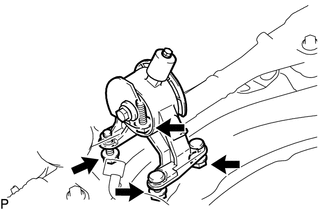
Remove the 2 bolts, 2 nuts and rear engine mounting insulator.
-
-
REMOVE ENGINE MOUNTING INSULATOR LH
Tech Tips
Perform this procedure only when replacement of the engine mounting insulator LH is necessary.
-
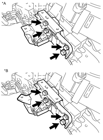
*A for Manual Transaxle *B for Automatic Transaxle Remove the 4 bolts and engine mounting insulator LH from the body.
-
-
REMOVE ENGINE MOUNTING INSULATOR SUB-ASSEMBLY RH
Tech Tips
Perform this procedure only when replacement of the engine mounting insulator sub-assembly RH is necessary.
-

Remove the 3 bolts and engine mounting insulator sub-assembly RH from the body.
-