ECD SYSTEM, Diagnostic DTC:P2016, P2017
| DTC Code | DTC Name |
|---|---|
| P2016 | Intake Manifold Runner Position Sensor/Switch Circuit Low Bank 1 |
| P2017 | Intake Manifold Runner Position Sensor/Switch Circuit High Bank 1 |
DESCRIPTION
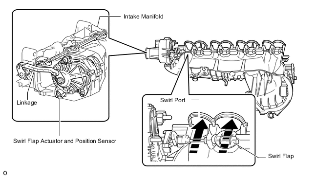
The swirl control valve is installed to the intake manifold and composed of the swirl flap, swirl flap actuator and swirl flap position sensor.
The position sensor is supplied with a voltage of 5 V by the ECM. The signal of the position sensor is an analogue voltage signal.
The controllable swirl flaps are located in the swirl ports. Depending on the operating range, the swirl flaps are activated with different duty cycles. The further the swirl flaps are closed, the more fresh air is drawn in exclusively through the swirl port. This increases the swirl of the drawn-in fresh air.
In the bottom load and engine speed range the swirl flaps are closed variably according to the operating range.
When the engine speed is approximately 2250 rpm or higher and the fuel injection volume is approximately 30 mg/stk or higher, the swirl flap is fully open.
The position of the swirl flaps is also corrected depending on the ambient pressure. At ambient pressures less than approximately 880 hPa, the swirl flaps tend to be opened further.
| DTC No. | Detection Item | DTC Detection Condition | Trouble Area | MIL | Memory |
|---|---|---|---|---|---|
| P2016 | Intake Manifold Runner Position Sensor/Switch Circuit Low Bank 1 | Swirl flap position sensor output voltage is 0.2 V or less for 0.22 seconds. (3 trip detection logic) |
|
Comes on | DTC stored |
| P2017 | Intake Manifold Runner Position Sensor/Switch Circuit High Bank 1 | Swirl flap position sensor output voltage is 4.85 V or more for 0.22 seconds. (3 trip detection logic) |
|
Comes on | DTC stored |
| DTC No. | Data List |
|---|---|
| P2016 P2017 |
Swirl Valve Actuator Position |
WIRING DIAGRAM
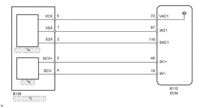
| *a | Position Sensor |
| *b | Actuator |
| *c | Swirl Control Valve |
CAUTION / NOTICE / HINT
Note
-
When replacing the ECM, the ECM needs registration and initialization.
-
After replacing the swirl control valve, the ECM needs initialization.
Tech Tips
-
When the ECM must be replaced, before replacing the ECM, perform the "Learning Values Save" function using the GTS. Then after installing the new ECM, perform all of the initialization/registrations for the "Learning Values Write" function by following the instructions shown on the GTS display.
-
Read freeze frame data using the GTS. Freeze frame data records the engine condition when malfunctions are detected. When troubleshooting, freeze frame data can help determine if the vehicle was moving or stationary, if the engine was warmed up or not, and other data from the time the malfunction occurred.
PROCEDURE
-
PERFORM ACTIVE TEST USING GTS (ACTUATOR TEST OF SWIRL FLAP)
-
Connect the GTS to the DLC3.
-
Turn the ignition switch to ON and turn the GTS on.
-
Start the engine.
-
Enter the following menus: Powertrain / Engine and ECT / Active Test / Actuator Test of Swirl Flap / Data List / Swirl Valve Actuator Position.
Powertrain > Engine and ECT > Active TestActive Test Display Actuator Test of Swirl Flap Data List Display Swirl Valve Actuator Position OK The value of "Swirl Valve Actuator Position" changes according to the amount "Actuator Test of Swirl Flap" is operated, and the swirl flap operates smoothly. Result Proceed to OK NG
OK 
GO TO STEP 8 Click here
NG 
-
-
CHECK HARNESS AND CONNECTOR (SWIRL CONTROL VALVE - ECM)
-
Disconnect the swirl control valve connector.
-
Disconnect the ECM connector.
-
Measure the resistance according to the value(s) in the table below.
Standard Resistance Tester Connection Condition Specified Condition B129-3 (SCV+) - B112-49 (IA1+) Always Below 1 Ω B129-4 (SCV-) - B112-19 (IA1-) Always Below 1 Ω B129-5 (VCX) - B112-72 (VAC1) Always Below 1 Ω B129-1 (VSX) - B112-87 (IAC1) Always Below 1 Ω B129-2 (E2X) - B112-119 (EAC1) Always Below 1 Ω B129-3 (SCV+) or B112-49 (IA1+) - Body ground Always 10 kΩ or higher B129-4 (SCV-) or B112-19 (IA1-) - Body ground Always 10 kΩ or higher B129-5 (VCX) or B112-72 (VAC1) - Body ground Always 10 kΩ or higher B129-1 (VSX) or B112-87 (IAC1) - Body ground Always 10 kΩ or higher Result Proceed to OK NG
NG
REPAIR OR REPLACE HARNESS OR CONNECTOR Click here
OK
-
-
CHECK HARNESS AND CONNECTOR (VC VOLTAGE)
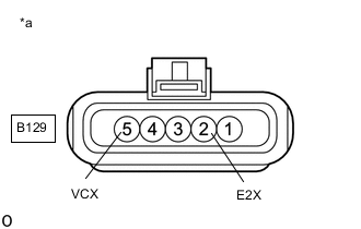
*a Front view of wire harness connector
(to Swirl Control Valve)
-
Disconnect the swirl control valve connector.
-
Turn the ignition switch to ON.
-
Measure the voltage according to the value(s) in the table below.
Standard Voltage Tester Connection Switch Condition Specified Condition B129-5 (VCX) - B129-2 (E2X) Ignition switch ON 4.5 to 5.5 V Result Proceed to OK NG
NG
REPLACE ECM Click here
OK
-
-
REPLACE SWIRL CONTROL VALVE
-
Replace the swirl control valve.
-
Perform the swirl valve learning value reset.
Result Proceed to NEXT
NEXT
-
-
CHECK WHETHER DTC OUTPUT RECURS (DTC P2016 AND/OR P2017)
-
Connect the GTS to the DLC3.
-
Turn the ignition switch to ON and turn the GTS on.
-
Clear the DTCs.
Powertrain > Engine and ECT > Clear DTCs -
Turn the ignition switch off and wait for 60 seconds or more [A].
-
Perform road test [B].
-
Repeat [A] and [B] for the number of trips detected.
-
Enter the following menus: Powertrain / Engine and ECT / Trouble Codes.
Powertrain > Engine and ECT > Trouble Codes -
Read the DTCs.
Result Result Proceed to No DTC output A DTC P2016 and/or P2017 B
A 
END
B
-
-
REPLACE ECM
-
Replace the ECM.
Result Proceed to NEXT
NEXT
GO TO STEP 8 Click here
-
-
REPAIR OR REPLACE HARNESS OR CONNECTOR
-
Repair or replace the harness or connector.
Result Proceed to NEXT
NEXT
-
-
CONFIRM WHETHER MALFUNCTION HAS BEEN SUCCESSFULLY REPAIRED
-
Connect the GTS to the DLC3.
-
Turn the ignition switch to ON and turn the GTS on.
-
Clear the DTCs.
Powertrain > Engine and ECT > Clear DTCs -
Turn the ignition switch off and wait for 60 seconds or more [A].
-
Perform road test [B].
-
Repeat [A] and [B] for the number of trips detected.
-
Enter the following menus: Powertrain / Engine and ECT / Trouble Codes.
Powertrain > Engine and ECT > Trouble Codes -
Confirm that the DTC is not output again.
Result Proceed to NEXT
NEXT
END
-