ECD SYSTEM, Diagnostic DTC:P2002
| DTC Code | DTC Name |
|---|---|
| P2002 | Diesel Particulate Filter Efficiency Below Threshold Bank 1 |
DESCRIPTION
Tech Tips
For more information on the diesel particulate filter (DPF) catalyst regeneration control, refer to System Description.
| DTC No. | Detection Item | DTC Detection Condition | Trouble Area | MIL | Memory |
|---|---|---|---|---|---|
| P2002 | Diesel Particulate Filter Efficiency Below Threshold Bank 1 | The fault is detected when the quotient of the integrated differential pressure and the integrated threshold value falls below a limit value. (3 trip detection logic) |
|
Comes on | DTC stored |
| DTC No. | Data List |
|---|---|
| P2002 | Adaptation Value of Differential Pressure at Particle Filter |
CAUTION / NOTICE / HINT
Note
-
When replacing the ECM, the ECM needs registration and initialization.
-
After replacing the DPF catalyst, the ECM needs initialization.
-
After replacing the differential pressure sensor, the ECM needs initialization.
Tech Tips
-
When the ECM must be replaced, before replacing the ECM, perform the "Learning Values Save" function using the GTS. Then after installing the new ECM, perform all of the initialization/registrations for the "Learning Values Write" function by following the instructions shown on the GTS display.
-
Read freeze frame data using the GTS. Freeze frame data records the engine condition when malfunctions are detected. When troubleshooting, freeze frame data can help determine if the vehicle was moving or stationary, if the engine was warmed up or not, and other data from the time the malfunction occurred.
PROCEDURE
-
CHECK HARNESS AND CONNECTOR (DIFFERENTIAL PRESSURE SENSOR - ECM)
-
Disconnect the differential pressure sensor connector.
-
Disconnect the ECM connector.
-
Measure the resistance according to the value(s) in the table below.
Standard Resistance Tester Connection Condition Specified Condition B127-1 (VC) - B112-70 (VCPX) Always Below 1 Ω B127-2 (PEX) - B112-85 (PEX) Always Below 1 Ω B127-3 (E2) - B112-71 (EPEX) Always Below 1 Ω B127-1 (VC) or B112-70 (VCPX) - Body ground Always 10 kΩ or higher B127-2 (PEX) or B112-85 (PEX) - Body ground Always 10 kΩ or higher B127-3 (E2) or B112-71 (EPEX) - Body ground Always 10 kΩ or higher Result Proceed to OK NG
NG 
REPAIR OR REPLACE HARNESS OR CONNECTOR Click here
OK 
-
-
CHECK HARNESS AND CONNECTOR (VC VOLTAGE)
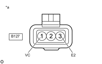
*a Front view of wire harness connector
(to Differential Pressure Sensor)
-
Disconnect the differential pressure sensor connector.
-
Turn the ignition switch to ON.
-
Measure the voltage according to the value(s) in the table below.
Standard Voltage Tester Connection Switch Condition Specified Condition B127-1 (VC) - B127-3 (E2) Ignition switch ON 4.5 to 5.5 V Result Proceed to OK NG
NG
REPLACE ECM Click here
OK
-
-
CHECK DIFFERENTIAL PRESSURE SENSOR AIR HOSE CONNECTION
-
Check hose pipes between exhaust system and differential pressure sensor. (for correct installation, arrangement (kinks), permeability (coking possible) and cracks).
OK Part is securely installed. Result Proceed to OK NG
NG
CONNECT AIR HOSE Click here
OK
-
-
CHECK EXHAUST MANIFOLD CONVERTER SUB-ASSEMBLY (DPF CATALYTIC CONVERTER)
-
Check that the DPF catalytic converter is installed.
OK DPF catalytic converter is installed. Tech Tips
If the DPF catalytic converter is not installed, the exhaust tailpipe turns black from soot.
-
Check that the DPF catalytic converter is not damaged.
OK DPF catalytic converter is not damaged. Tech Tips
If the DPF catalytic converter is not installed, the exhaust tailpipe turns black from soot.
-
If the DPF catalytic converter is damaged, the exhaust tailpipe and edge of the filter turn black from soot.
-
Disconnect the front exhaust pipe assembly from the exhaust manifold converter sub-assembly (DPF catalytic converter) and check for soot stuck inside the exhaust manifold converter sub-assembly (DPF catalytic converter).
Result Proceed to OK NG -
NG
INSTALL OR REPLACE EXHAUST MANIFOLD CONVERTER SUB-ASSEMBLY (DPF CATALYTIC CONVERTER) Click here
OK
-
-
REPLACE DIFFERENTIAL PRESSURE SENSOR
-
Replace the differential pressure sensor.
-
Perform the differential pressure learning value reset.
Result Proceed to NEXT
NEXT
-
-
CHECK WHETHER DTC OUTPUT RECURS (DTC P2002)
-
Connect the GTS to the DLC3.
-
Turn the ignition switch to ON and turn the GTS on.
-
Clear the DTCs.
Powertrain > Engine and ECT > Clear DTCs -
Turn the ignition switch off and wait for 60 seconds or more [A].
-
Perform road test [B].
-
Repeat [A] and [B] for the number of trips detected.
-
Enter the following menus: Powertrain / Engine and ECT / Trouble Codes.
Powertrain > Engine and ECT > Trouble Codes -
Read the DTCs.
Result Result Proceed to No DTC output A DTC P2002 B
A 
END
B
GO TO STEP 9 Click here
-
-
INSTALL OR REPLACE EXHAUST MANIFOLD CONVERTER SUB-ASSEMBLY (DPF CATALYTIC CONVERTER)
-
Install or replace the exhaust manifold converter sub-assembly (DPF catalytic converter).
-
Perform DPF history information reset and NOx storage catalyst learning value reset.
Result Proceed to NEXT
NEXT
GO TO STEP 11 Click here
-
-
CONNECT AIR HOSE
-
Install the air hose.
Result Proceed to NEXT
NEXT
GO TO STEP 11 Click here
-
-
REPLACE ECM
-
Replace the ECM.
Result Proceed to NEXT
NEXT
GO TO STEP 11 Click here
-
-
REPAIR OR REPLACE HARNESS OR CONNECTOR
-
Repair or replace the harness or connector.
Result Proceed to NEXT
NEXT
-
-
CONFIRM WHETHER MALFUNCTION HAS BEEN SUCCESSFULLY REPAIRED
-
Connect the GTS to the DLC3.
-
Turn the ignition switch to ON and turn the GTS on.
-
Clear the DTCs.
Powertrain > Engine and ECT > Clear DTCs -
Turn the ignition switch off and wait for 60 seconds or more [A].
-
Perform road test [B].
-
Repeat [A] and [B] for the number of trips detected.
-
Enter the following menus: Powertrain / Engine and ECT / Trouble Codes.
Powertrain > Engine and ECT > Trouble Codes -
Confirm that the DTC is not output again.
Result Proceed to NEXT
NEXT
END
-