ECD SYSTEM(for DPF), Diagnostic DTC:P0488
| DTC Code | DTC Name |
|---|---|
| P0488 | Exhaust Gas Recirculation Throttle Position Control Range / Performance |
DESCRIPTION
The ECM opens and closes the throttle valve using a DC motor type actuator. Due to the opening and closing of the valve, the exhaust gas recirculation volume can be properly controlled. Also, engine vibration and noise will be reduced by closing the valve when the engine is stopped.
Although the DTC title says "Exhaust Gas Recirculation Throttle Position Control Range / Performance", this DTC indicates that the throttle valve is malfunctioning.
| DTC No. | Detection Item | DTC Detection Condition | Trouble Area | MIL | Memory |
|---|---|---|---|---|---|
| P0488 | Exhaust Gas Recirculation Throttle Position Control Range / Performance | The throttle motor activation duty is more than specified value for 30 seconds (1 trip detection logic). |
|
Comes on | DTC stored |
| DTC No. | Data List |
|---|---|
| P0488 |
|
| Condition | Throttle Valve Position |
|---|---|
| Moment when accelerator pedal is depressed further or released at 3000 rpm | Throttle valve opening angle varies smoothly |
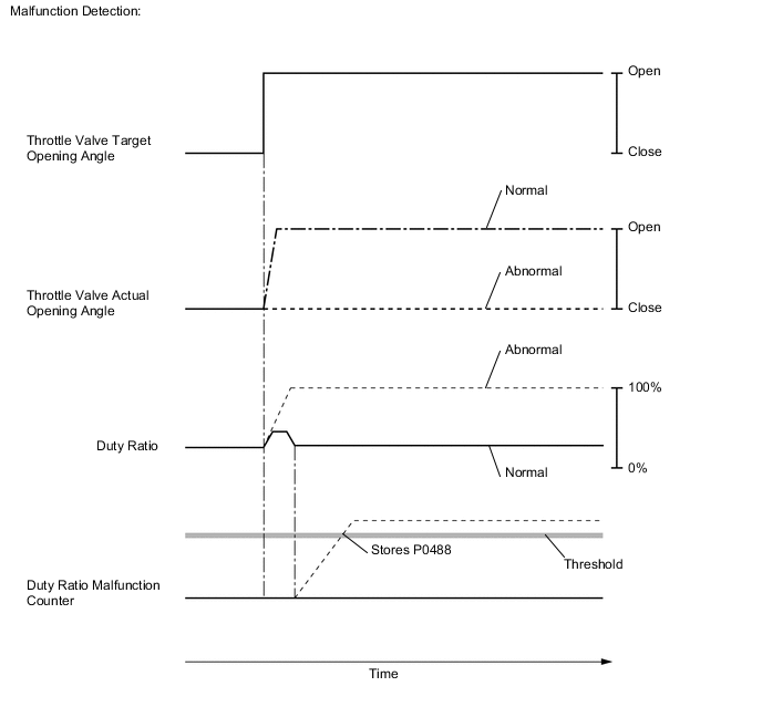
MONITOR DESCRIPTION
The ECM opens and closes the throttle valve by adjusting the current flowing to the DC motor with a duty ratio. If the throttle valve does not move smoothly or is stuck, the duty ratio used during valve movement control increases or decreases greatly. The ECM will determine that the throttle valve is malfunctioning and illuminate the MIL.
| Throttle Condition | Target Throttle Position | Actual Throttle Position | Throttle Close Learning Val. | Diesel Throttle Learn Status |
|---|---|---|---|---|
| Throttle Valve Fully Closed | 100% | 100% | 14.25 to 21.25 deg | OK |
| Throttle Valve Fully Open | 0% | 0% |
Tech Tips
-
If carbon deposits exist in the diesel throttle body assembly, the following parts possibly also have deposits inside: The electric EGR control valve assembly, intake manifold, exhaust fuel addition injector, DPF catalyst, and other parts related to the exhaust gas.
By removing the electric EGR control valve assembly from the intake manifold, the carbon deposit condition between the EGR valve and intake manifold can be checked visually. When checking for deposits in the electric EGR control valve assembly, hold the EGR valve to a light and confirm that the valve contacts the valve seat securely.
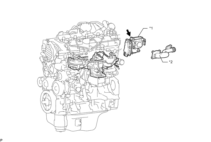
*1 Electric EGR Control Valve Assembly *2 No. 2 EGR Pipe -
DPF catalyst diagnosis:
The value of "Catalyst Differential Press" in the Data List is high when the catalyst is clogged. If this value exceeds approximately 0.4, DTC P244B is stored.
If the "Catalyst Differential Press" become near about 0.4, the catalyst is probably clogged with PM even if DTC P244B is not stored.
Check the Catalyst Differential Press when the engine is running at 3000 rpm with no load. Enter the following menus: Powertrain / Engine and ECT / Data List / Catalyst Differential Press.
If the value of MAF in the Data List is less than 25 gm/s, a correct value for Catalyst Differential Press is not output due to exhaust gas pulsation.
-
Exhaust fuel addition injector assembly diagnosis:
When the fuel volume injected by the exhaust fuel addition injector assembly decreases, the value of "Exhaust Fuel Addition FB" in the Data List increases. Exhaust Fuel Addition FB in the Data List is a correction value to increase the fuel volume injected from the exhaust fuel addition injector assembly when the catalyst temperature does not rise to the target during catalyst regeneration. Under normal conditions, the value is between 0.9 and 1.45.
Check the value by entering the following menus on the GTS: Powertrain / Engine and ECT / Data List / Exhaust Fuel Addition FB. Under normal conditions, the exhaust gas temperature becomes 150 to 350°C (302 to 662°F) when the vehicle is driven in 3rd gear at a constant vehicle speed of about 50 km/h (31 mph). While driving under these conditions, the exhaust gas temperature rises to 500 to 700°C (932 to 1292°F) when the catalyst regeneration function in the Active Test (Activate the DPF Rejuvenate (PM)) is performed. If the temperature does not rise sufficiently, the exhaust fuel addition injector assembly or the DPF catalyst may be damaged.
CONFIRMATION DRIVING PATTERN
| DTC No. | DTC Detection Drive Pattern |
|---|---|
| P0488 | Perform the following repeatedly for 1 minute: gradually raise the engine speed to 3000 rpm from an idling over approximately 10 seconds, and then release the accelerator pedal to return to an idling state. |
WIRING DIAGRAM
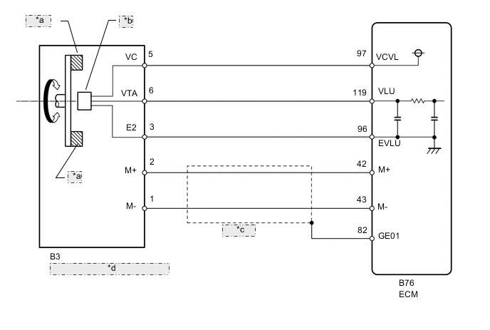
| *a | Magnet |
| *b | Hall IC |
| *c | Shielded |
| *d | Diesel Throttle Body Assembly |
CAUTION / NOTICE / HINT
Note
-
When cleaning the EGR valve or diesel throttle body, use a piece of cloth soaked with cleaning solvent. Spraying the solvent directly onto these parts or soaking the parts in solvent may damage the parts.
-
After replacing the ECM, the new ECM needs registration (Click here ) and initialization Click here.
PROCEDURE
-
CHECK ANY OTHER DTCS OUTPUT (IN ADDITION TO DTC P0488)
-
Connect the GTS to the DLC3.
-
Turn the ignition switch to ON and turn the GTS on.
-
Enter the following menus: Powertrain / Engine and ECT / Trouble Codes.
Powertrain > Engine > Trouble Codes -
Read the DTCs.
Result Proceed to DTC P0488 is output DTC P0488 and other DTCs are output Tech Tips
-
If any DTCs other than DTC P0488 are output, troubleshoot those DTCs first.
-
Be sure to also record the values of "Actual Throttle Position" and "Target Throttle Position" listed in the freeze frame data.
-
DTC P0488 and other DTCs are output 
GO TO DTC CHART Click here
DTC P0488 is output 
-
-
READ VALUE USING GTS (DIESEL THROTTLE LEARN STATUS)
-
Connect the GTS to the DLC3.
-
Turn the ignition switch to ON and turn the GTS on.
-
Clear the DTCs.
Powertrain > Engine > Clear DTCs -
Turn the ignition switch off for 30 seconds or more.
Tech Tips
Be sure to turn off the ignition switch before performing this inspection. The fully closed position of the diesel throttle valve is learned when the ignition switch is turned off.
-
Enter the following menus: Powertrain / Engine and ECT / Data List / Diesel Throttle Learn Status.
Powertrain > Engine > Data ListTester Display Diesel Throttle Learn Status -
Read the values when the ignition switch is ON.
Standard Diesel Throttle Learn Status is OK Note
Extremely cold conditions might cause the throttle valve movement to be delayed.
Result Proceed to OK NG
NG 
REMOVE DEPOSIT (CLEAN EGR PASSAGE) Click here
OK
-
-
PERFORM ACTIVE TEST USING GTS (DIESEL THROTTLE TARGET ANGLE)
-
Connect the GTS to the DLC3.
-
Turn the ignition switch to ON and turn the GTS on.
-
Enter the following menus: Powertrain / Engine and ECT / Active Test / Diesel Throttle Target Angle.
Powertrain > Engine > Active TestTester Display Diesel Throttle Target Angle -
When changing the Active Test continuously value to 0, 30, 60, 90, 60, 30 and 0%, check that Actual Throttle Position smoothly changes to the set opening angle.
OK Value smoothly changes to set opening angle. Result Proceed to OK NG
NG
GO TO STEP 8 Click here
OK
-
-
REMOVE DEPOSIT (CLEAN EGR PASSAGE)
-
Remove the electric EGR control valve assembly, No. 2 intake manifold and intake manifold.
-
Remove the deposits from those parts and clean the parts.
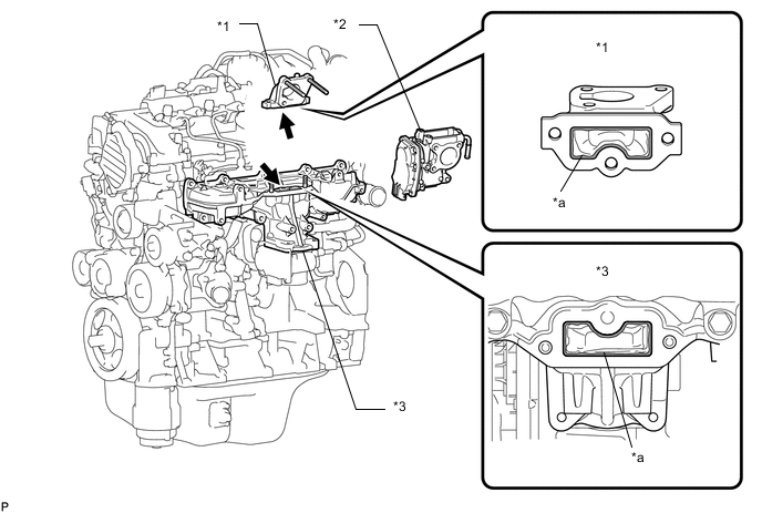
*1 No. 2 Intake Manifold *2 Electric EGR Control Valve Assembly *3 Intake Manifold - - *a Carbon Deposit - - Note
-
When cleaning the EGR valve and diesel throttle body, use a piece of cloth soaked with cleaning solvent. Spraying the solvent directly onto these parts or soaking the parts in solvent may damage the parts.
-
Extreme care must be taken to prevent the removed deposits from falling into the engine unit during cleaning.
Tech Tips
Remove the intake manifold from the cylinder head when it has to be cleaned.
Result Proceed to NEXT -
NEXT
-
-
INSPECT DIESEL THROTTLE BODY ASSEMBLY (THROTTLE VALVE MOVEMENT)
-
Using your finger, move the throttle valve from the fully open position to the fully closed position and check that it moves smoothly.
OK Throttle valve moves smoothly. Note
Take care not to damage the throttle valve or valve housing.
Result Proceed to OK NG
OK
GO TO STEP 7 Click here
NG
-
-
REPLACE DIESEL THROTTLE BODY ASSEMBLY
-
Replace the diesel throttle body assembly.
Result Proceed to NEXT
NEXT
-
-
CHECK WHETHER DTC OUTPUT RECURS (DTC P0488)
-
Start the engine and warm it up.
-
Connect the GTS to the DLC3.
-
Turn the GTS on.
-
Enter the following menus: Powertrain / Engine and ECT / Data List / Engine Speed, Target Throttle Position and Actual Throttle Position.
Powertrain > Engine > Data ListTester Display Engine Speed Target Throttle Position Actual Throttle Position -
Take a snapshot with the GTS.
-
Enter the following menus: Powertrain / Engine and ECT / Active Test / Diesel Throttle Target Angle.
Powertrain > Engine > Active TestTester Display Diesel Throttle Target Angle Tech Tips
The movement of the throttle valve can be determined by performing the following inspection.
-
When changing the Active Test value continuously to 0, 30, 60, 90, 60, 30 and 0%, check that Actual Throttle Position smoothly changes to the set opening angle.
OK Value smoothly changes to set opening angle. -
Perform the following repeatedly for 1 minute: gradually raise the engine speed to 3000 rpm from an idling over approximately 10 seconds, and then release the accelerator pedal to return to an idling state.
-
Enter the following menus: Powertrain / Engine and ECT / Trouble Codes.
Powertrain > Engine > Trouble Codes -
Read the DTCs.
OK DTC is not output. Result Proceed to OK NG
OK
END
NG
REPLACE ECM Click here
-
-
REMOVE DEPOSIT (CLEAN EGR PASSAGE)
-
Remove the EGR valve assembly, No. 2 intake manifold and intake manifold.
-
Remove the deposits from those parts and clean the parts.
*1 No. 2 Intake Manifold *2 Electric EGR Control Valve Assembly *3 Intake Manifold - - *a Carbon Deposit - - Note
-
When cleaning the EGR valve and diesel throttle body, use a piece of cloth soaked with cleaning solvent. Spraying the solvent directly onto these parts or soaking the parts in solvent may damage the parts.
-
Extreme care must be taken to prevent the removed deposits from falling into the engine unit during cleaning.
Tech Tips
Remove the intake manifold from the cylinder head when it has to be cleaned.
-
-
Reinstall the EGR valve assembly, No. 2 intake manifold and intake manifold.
Result Proceed to NEXT
NEXT
-
-
INSPECT DIESEL THROTTLE BODY ASSEMBLY (THROTTLE VALVE MOVEMENT)
-
Using your finger, move the throttle valve from the fully open position to the fully closed position and check that it moves smoothly.
OK Throttle valve moves smoothly. Note
Take care not to damage the throttle valve or valve housing.
Result Proceed to OK NG
NG
GO TO STEP 6 Click here
OK
-
-
CHECK HARNESS AND CONNECTOR (ECM - DIESEL THROTTLE BODY ASSEMBLY)
-
Disconnect the diesel throttle body assembly connector.
-
Disconnect the ECM connector.
-
Measure the resistance according to the value(s) in the table below.
Standard Resistance Tester Connection Condition Specified Condition B3-5 (VC) - B76-97 (VCVL) Always Below 1 Ω B3-6 (VTA) - B76-119 (VLU) Always Below 1 Ω B3-3 (E2) - B76-96 (EVLU) Always Below 1 Ω B3-2 (M+) - B76-42 (M+) Always Below 1 Ω B3-1 (M-) - B76-43 (M-) Always Below 1 Ω B3-5 (VC) or B76-97 (VCVL) - Body ground Always 10 kΩ or higher B3-6 (VTA) or B76-119 (VLU) - Body ground Always 10 kΩ or higher B3-3 (E2) or B76-96 (EVLU) - Body ground Always 10 kΩ or higher B3-2 (M+) or B76-42 (M+) - Body ground Always 10 kΩ or higher B3-1 (M-) or B76-43 (M-) - Body ground Always 10 kΩ or higher Result Proceed to OK NG
OK
GO TO STEP 6 Click here
NG
REPAIR OR REPLACE HARNESS OR CONNECTOR Click here
-
-
REPLACE ECM
-
Replace the ECM.
Result Proceed to NEXT
NEXT
-
-
CHECK WHETHER DTC OUTPUT RECURS (DTC P0488)
-
Start the engine and warm it up.
-
Connect the GTS to the DLC3.
-
Turn the GTS on.
-
Enter the following menus: Powertrain / Engine and ECT / Data List / Engine Speed, Target Throttle Position and Actual Throttle Position.
Powertrain > Engine > Data ListTester Display Engine Speed Target Throttle Position Actual Throttle Position -
Take a snapshot with the GTS.
-
Enter the following menus: Powertrain / Engine and ECT / Active Test / Diesel Throttle Target Angle.
Powertrain > Engine > Active TestTester Display Diesel Throttle Target Angle Tech Tips
The movement of the throttle valve can be determined by performing the following inspection.
-
When changing the Active Test value continuously to 0, 30, 60, 90, 60, 30 and 0%, check that Actual Throttle Position smoothly changes to the set opening angle.
OK Value smoothly changes to set opening angle. -
Perform the following repeatedly for 1 minute: gradually raise the engine speed to 3000 rpm from an idling over approximately 10 seconds, and then release the accelerator pedal to return to an idling state.
-
Enter the following menus: Powertrain / Engine and ECT / Trouble Codes.
Powertrain > Engine > Trouble Codes -
Confirm that the DTC is not output again.
Result Proceed to NEXT
NEXT
END
-
-
REPAIR OR REPLACE HARNESS OR CONNECTOR
-
Repair or replace the harness or connector.
Result Proceed to NEXT
NEXT
GO TO STEP 12 Click here
-