ДАТЧИК ТЕМПЕРАТУРЫ ОТРАБОТАВШИХ ГАЗОВ (для моделей с контроллером свечей накаливания) СНЯТИЕ
PROCEDURE
-
PRECAUTION
Note
After turning the ignition switch off, waiting time may be required before disconnecting the cable from the negative (-) battery terminal. Therefore, make sure to read the disconnecting the cable from the negative (-) battery terminal notices before proceeding with work.
-
DISCONNECT CABLE FROM NEGATIVE BATTERY TERMINAL
Note
When disconnecting the cable, some systems need to be initialized after the cable is reconnected.
-
REMOVE NO. 1 ENGINE COVER (w/ No. 1 Engine Cover)
-
REMOVE WINDSHIELD WIPER MOTOR AND LINK ASSEMBLY
-
REMOVE WATER GUARD PLATE LH
-
for LHD:
-
for RHD:
-
-
REMOVE NO. 2 HEATER AIR DUCT SPLASH SHIELD SEAL
-
for LHD:
-
for RHD:
-
-
REMOVE OUTER COWL TOP PANEL
-
for LHD:
-
for RHD:
-
-
REMOVE NO. 1 WIRE HARNESS HEAT INSULATOR
-
REMOVE WIRE HARNESS CLAMP BRACKET
-
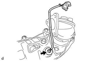
REMOVE EXHAUST GAS TEMPERATURE SENSOR
Note
If the exhaust gas temperature sensor is dropped, replace it with a new one.
-
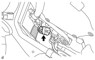
Disconnect the exhaust gas temperature sensor connector.
-
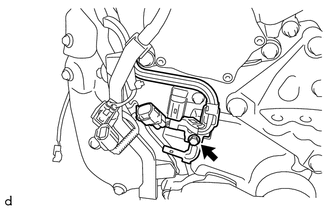
Remove the bolt and wire harness clamp bracket from the timing chain cover assembly.
-
Disengage the claw to disconnect the exhaust gas temperature sensor connector from the wire harness clamp bracket.
-
Disengage the clamp to disconnect the wire harness from the wire harness clamp bracket.
-
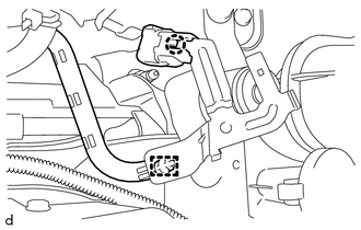
Using a 14 mm union nut wrench, remove the exhaust gas temperature sensor from the No. 2 exhaust manifold.
-
-
REMOVE DIFFERENTIAL PRESSURE SENSOR ASSEMBLY
-
REMOVE SENSOR BRACKET
-
REMOVE NO. 2 ENGINE COVER BRACKET
-
SEPARATE NO. 2 HOSE TO HOSE TUBE (for LHD)
-
SEPARATE NO. 2 HOSE TO HOSE TUBE (for RHD)
-
REMOVE BATTERY
-
REMOVE AIR CLEANER CAP SUB-ASSEMBLY
-
REMOVE AIR CLEANER CASE SUB-ASSEMBLY
-
REMOVE NO. 1 AIR TUBE
-
REMOVE NO. 1 TURBO INSULATOR
-
REMOVE FRONT DRIVE SHAFT ASSEMBLY RH
-
REMOVE FRONT CENTER FLOOR BRACE SUB-ASSEMBLY
-
REMOVE FRONT EXHAUST PIPE ASSEMBLY
-
REMOVE FRONT NO. 1 FLOOR HEAT INSULATOR
-
REMOVE NO. 5 MANIFOLD SUPPORT BRACKET
-
REMOVE FRONT SUSPENSION CROSSMEMBER SUB-ASSEMBLY
-
REMOVE NO. 4 MANIFOLD SUPPORT BRACKET
-
REMOVE DRIVE SHAFT HEAT INSULATOR SUB-ASSEMBLY
-
REMOVE NO. 2 EXHAUST MANIFOLD
-
REMOVE NO. 2 EXHAUST GAS TEMPERATURE SENSOR
Note
If the No. 2 exhaust gas temperature sensor is dropped, replace it with a new one.
-
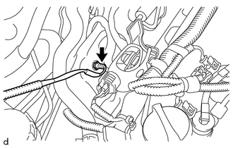
Using a 14 mm union nut wrench, remove the No. 2 exhaust gas temperature sensor from the No. 2 exhaust manifold.
-