ДВИГАТЕЛЬ ПРОВЕРКА БЕЗ СНЯТИЯ С АВТОМОБИЛЯ

PROCEDURE
-
INSPECT ENGINE COOLANT
-
INSPECT ENGINE OIL
-
INSPECT BATTERY
-
INSPECT AIR CLEANER FILTER ELEMENT SUB-ASSEMBLY
-
Remove the air cleaner cap sub-assembly.
-
Remove the air filter element sub-assembly.
-
Visually check that the air cleaner filter element sub-assembly is not excessively damaged or oily. If necessary, replace the air cleaner filter element sub-assembly.
Tech Tips
-
If there is any foreign matter or clogs in the air cleaner filter element sub-assembly, clean it with compressed air.
-
If any foreign matter or clogs remain even after cleaning the air cleaner filter element sub-assembly with compressed air, replace it.
-
-
Install the air cleaner filter element sub-assembly.
-
Install the air cleaner cap sub-assembly.
-
-
INSPECT V-RIBBED BELT
-
INSPECT ENGINE SPEED
Note
-
Turn all the electrical systems and the A/C off.
-
Inspect the engine idle speed with the cooling fan off.
-
When checking the idle speed, the transaxle should be in neutral.
-
Warm up and stop the engine.
-
When using the GTS:
-
Connect the GTS to the DLC3.
-
Turn the ignition switch to ON.
-
Start the engine.
-
Turn the GTS on.
-
Enter the following menus: Powertrain / Engine and ECT / Data List / Engine Speed.
Powertrain > Engine and ECT > Data ListTester Display Engine Speed -
Inspect the engine idle speed.
Standard Idle Speed 720 to 820 rpm -
Fully depress the accelerator pedal.
-
Inspect the maximum engine speed.
Maximum Speed 5150 to 5250 rpm -
Turn the ignition switch off.
-
Disconnect the GTS from the DLC3.
-
-
When not using the GTS:
-
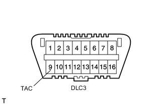
Using SST, connect a tachometer probe to terminal 9 (TAC) of the DLC3.
- SST
- 09843-18040
Note
Be sure to connect the tachometer to the correct terminal. Connecting the wrong terminals can cause damage.
-
Turn the ignition switch to ON.
-
Start the engine.
-
Inspect the engine idle speed.
Standard Idle Speed 720 to 820 rpm -
Fully depress the accelerator pedal.
-
Inspect the maximum engine speed.
Maximum Speed 5150 to 5250 rpm -
Turn the ignition switch off.
-
Disconnect the tachometer probe from terminal 9 (TAC) of the DLC3.
-
-
-
INSPECT COMPRESSION
-
Warm up and stop the engine.
-
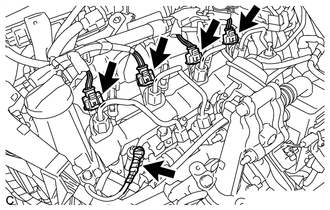
Disconnect the 4 connectors from the 4 injector assemblies.
-
Remove the 4 glow plug assemblies.
Note
In order to avoid shorting the circuit of the wire harness connected to the glow plug No. 1 connector, wind vinyl tape around the wire harness terminal portion.
-
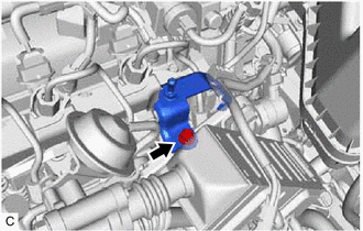
Remove the bolt and separate the No. 3 engine cover bracket.
-
Connect the cable to the negative (-) battery terminal.
-
Crank the engine to remove foreign matter before measuring the compression.
-
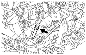
*a SST (Attachment) Install the SST (attachment) into the glow plug assembly hole.
- SST
- 09992-00026 ( 09992-00121, 09992-00160 )
- Torque:
- 13 N*m { 133 kgf*cm, 10 ft.*lbf }
-
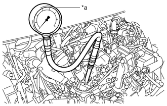
*a SST (Compression Gauge) Connect a SST (compression gauge) to the SST (attachment).
- SST
- 09992-00026 ( 09992-00211 )
-
While cranking the engine, measure the compression pressure.
Compression Pressure 2300 kPa (23.5 kgf/cm2, 334 psi) Minimum Pressure 2050 kPa (20.9 kgf/cm2, 297psi) Difference Between Each Cylinder 500 kPa (5.1 kgf/cm2, 73 psi) or less Note
-
Use a fully-charged battery so that the engine speed can be increased to 250 rpm or more.
-
Inspect the other cylinders in the same way.
-
Measure the compression pressure in as short a time as possible.
If the cylinder compression is low, pour a small amount of engine oil into the cylinder through the glow plug assembly hole, and then inspect it again.
Tech Tips
-
If adding oil increases the compression, the piston rings and/or cylinder bore may be worn or damaged.
-
If the compression pressure stays low, a valve may be stuck or seated improperly, or there may be leaks in the cylinder head gasket.
-
-
Remove the SST (compression gauge and attachment).
-
Install the No. 3 engine cover bracket with the bolt.
- Torque:
- 9.0 N*m { 92 kgf*cm, 80 in.*lbf }
-
Install the 4 glow plug assemblies.
-
Connect the 4 connectors to the 4 injector assemblies.
-