ТОПЛИВНАЯ СИСТЕМА ДВИГАТЕЛЯ COMMON RAIL (для моделей с контроллером свечей накаливания) СНЯТИЕ
CAUTION / NOTICE / HINT
Note
-
When replacing the injector assemblies (including exchanging the injector assemblies between the cylinders), common rail assembly, intake manifold or cylinder head sub-assembly, it is necessary to replace the injection pipe sub-assemblies with new ones.
-
When replacing the injector assemblies, supply pump assembly, common rail assembly, intake manifold or cylinder head sub-assembly, it is necessary to replace the fuel inlet pipe sub-assembly with a new one.
PROCEDURE
-
REMOVE NO. 1 ENGINE COVER (w/ No. 1 Engine Cover)
-
REMOVE AIR CLEANER CAP SUB-ASSEMBLY
-
REMOVE NO. 1 GLOW PLUG CONNECTOR
-
REMOVE NO. 1 VACUUM SWITCHING VALVE ASSEMBLY
-
REMOVE NOZZLE LEAKAGE PIPE ASSEMBLY
Note
Perform installation and removal procedures by hand only. Do not use any tools.
-
Slide the clip and disconnect the nozzle leakage pipe assembly from the No. 2 nozzle leakage pipe.
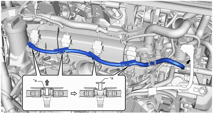
*a Lock Bush - - 
Pull up - - -
Disengage the clamp to disconnect the nozzle leakage pipe assembly from the hose clamp.
-
Pull up the 4 lock bushes of the nozzle leakage pipe assembly as shown in the illustration, and remove it from each injector assembly.
-
-
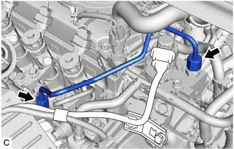
REMOVE NO. 1 INJECTION PIPE SUB-ASSEMBLY
-
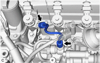
Using a 17 mm union nut wrench, loosen the 2 union nuts, and remove the No. 1 injection pipe sub-assembly from the injector assembly and common rail assembly.
Note
To prevent contamination by foreign matter, after removing the No. 1 injection pipe sub-assembly, protect the connecting portions of the injector assembly and common rail assembly with plastic bags.
-
-
REMOVE NO. 2 INJECTION PIPE SUB-ASSEMBLY
-
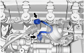
Using a 17 mm union nut wrench, loosen the 2 union nuts, and remove the No. 2 injection pipe sub-assembly from the injector assembly and common rail assembly.
Note
To prevent contamination by foreign matter, after removing the No. 2 injection pipe sub-assembly, protect the connecting portions of the injector assembly and common rail assembly with plastic bags.
-
-
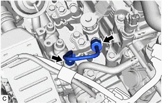
REMOVE NO. 3 INJECTION PIPE SUB-ASSEMBLY
-
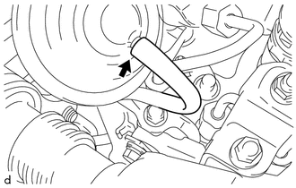
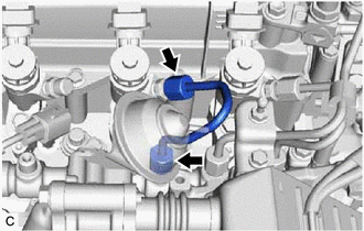
Disconnect the vacuum hose from the No. 2 EGR valve assembly.
-
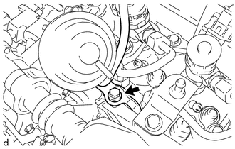
Remove the bolt and separate the vacuum transmitting pipe sub-assembly from the EGR cooler bracket.
-
Using a 17 mm union nut wrench, loosen the 2 union nuts, and remove the No. 3 injection pipe sub-assembly from the injector assembly and common rail assembly.
Note
To prevent contamination by foreign matter, after removing the No. 3 injection pipe sub-assembly, protect the connecting portions of the injector assembly and common rail assembly with plastic bags.
-
-
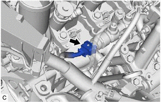
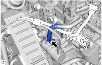
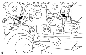
REMOVE FUEL INLET PIPE SUB-ASSEMBLY
-
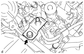
Remove the bolt and No. 3 engine cover bracket from the EGR cooler bracket.
-
Remove the bolt and No. 2 injection pipe clamp from the fuel inlet pipe sub-assembly and No. 4 injection pipe sub-assembly.
-
Using a 17 mm union nut wrench, loosen the 2 union nuts, and remove the fuel inlet pipe sub-assembly from the injector assembly and common rail assembly.
Note
To prevent contamination by foreign matter, after removing the fuel inlet pipe sub-assembly, protect the connecting portions of the injector assembly and common rail assembly with plastic bags.
-
-
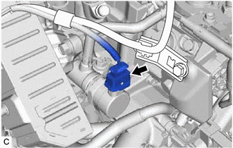
REMOVE NO. 4 INJECTION PIPE SUB-ASSEMBLY
-
Using a 17 mm union nut wrench, loosen the 2 union nuts, and remove the No. 4 injection pipe sub-assembly from the injector assembly and common rail assembly.
Note
To prevent contamination by foreign matter, after removing the No. 4 injection pipe sub-assembly, protect the connecting portions of the injector assembly and common rail assembly with plastic bags.
-
-
REMOVE COMMON RAIL ASSEMBLY
-
Disconnect the rail pressure sensor connector.
-
Disconnect the pressure control valve connector.
-
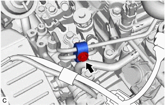
Slide the clip and disconnect the No. 2 fuel hose from the common rail assembly.
-
Remove the 2 bolts.
-
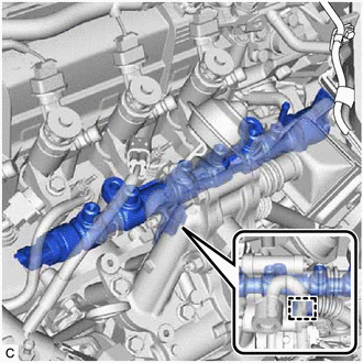
Disengage the clamp, and while disconnecting the No. 4 water by-pass hose, remove the common rail assembly from the cylinder head sub-assembly.
-
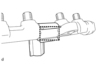
Disengage the clamp to remove the hose clamp from the common rail assembly.
-