СИСТЕМА ECD (для моделей с контроллером свечей накаливания), Diagnostic DTC:P052F, P0683
| DTC Code | DTC Name |
|---|---|
| P052F | Glow Plug Control Module System Voltage |
| P0683 | Glow Plug Control Module to PCM Communication Circuit |
DESCRIPTION
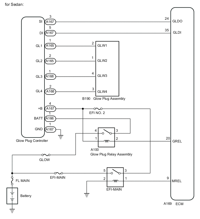
The glow system consists of the glow plug controller, glow plug assemblies and ECM. The glow plug controller turns on the glow plug assembly of each cylinder according to the duty command signal from the ECM in order to maintain optimal engine temperatures. The glow plug assemblies can be controlled according to the engine coolant temperature at engine start by using duty signals. This helps induce ignition under low temperatures and prevent rough idle after starting the engine.
The glow plug assemblies are turned on during PM forced regeneration in order to prevent the engine speed from rising due to an increase in fuel injection volume used to increase the exhaust gas temperature. The glow plug controller contains a self-diagnosis function. When the glow plug controller detects an internal malfunction, it sends a signal indicating the malfunction to the ECM. When the ECM receives this signal, it illuminates the MIL and stores a DTC.
| DTC No. | Detection Item | DTC Detection Condition | Trouble Area | MIL | Memory |
|---|---|---|---|---|---|
| P052F | Glow Plug Control Module System Voltage | The glow plug controller recognizes the battery voltage as being 18.4 V or higher 3 times or more when the glow plug assemblies are on (2 trip detection logic). | Glow plug controller | Comes on | DTC stored |
| P0683 | Glow Plug Control Module to PCM Communication Circuit | When the glow plug assemblies are on, the ECM detects that there is no output from the glow plug control unit for 3 seconds even though the ECM outputs an SI signal ("ON" command signal) (2 trip detection logic). |
|
Comes on | DTC stored |
| DTC No. | DTC Detection Drive Pattern |
|---|---|
| P052F | Ignition switch ON |
| P0683 |
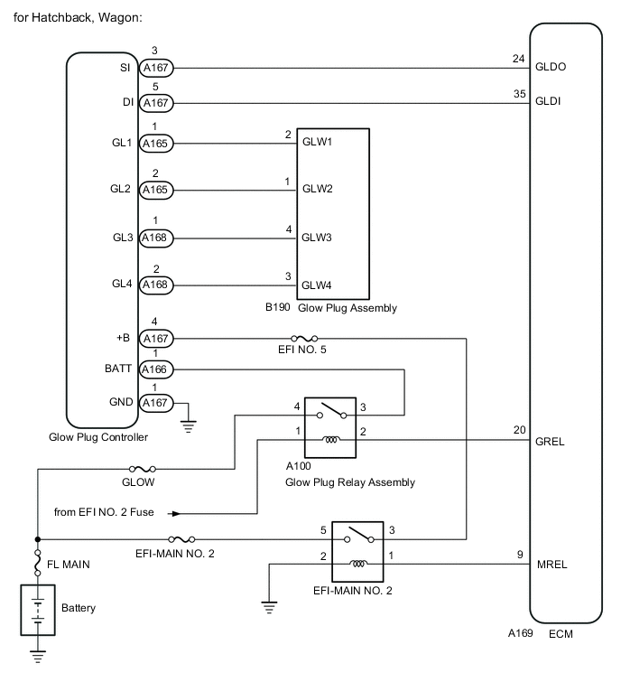
WIRING DIAGRAM
CAUTION / NOTICE / HINT
Note
-
When replacing the ECM, perform ECM Initialization and Registration.
-
Inspect the fuses of circuits related to this system before performing the following procedure.
Tech Tips
-
When the ECM must be replaced, before replacing the ECM, perform the "Learning Values Save" function using the GTS. Then after installing a new ECM, perform all of the initialization and registration procedures for the "Learning Values Write" function by following the instructions shown on the GTS display.
-
Read freeze frame data using the GTS. Freeze frame data records the engine condition when malfunctions are detected. When troubleshooting, freeze frame data can help determine if the vehicle was moving or stationary, if the engine was warmed up or not, and other data from the time the malfunction occurred.
PROCEDURE
-
CHECK DTC OUTPUT
-
Connect the GTS to the DLC3.
-
Turn the ignition switch to ON and turn the GTS on.
-
Enter the following menus: Powertrain / Engine and ECT / Trouble Codes.
-
Read the DTCs.
Powertrain > Engine and ECT > Trouble CodesResult Result Proceed to DTC P0683 is output A DTC P052F is output B
B 
REPLACE GLOW PLUG CONTROLLER Click here
A 
-
-
CHECK TERMINAL VOLTAGE (POWER SOURCE OF GLOW PLUG CONTROLLER)
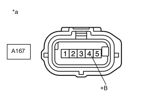
*a Front view of wire harness connector
(to Glow Plug Controller)
-
Disconnect the glow plug controller connector.
-
Turn the ignition switch to ON.
-
Measure the voltage according to the value(s) in the table below.
Standard Voltage Tester Connection Condition Specified Condition A167-4 (+B) - Body ground Ignition switch ON 11 to 14 V A167-4 (+B) - Body ground Ignition switch off Below 0.5 V Result Result Proceed to OK A NG (for sedan) B NG (for hatchback, wagon) C
B
CHECK HARNESS AND CONNECTOR (EFI-MAIN RELAY - GLOW PLUG CONTROLLER) Click here
C
CHECK HARNESS AND CONNECTOR (EFI-MAIN NO. 2 RELAY - GLOW PLUG CONTROLLER) Click here
A
-
-
CHECK HARNESS AND CONNECTOR (GLOW PLUG CONTROLLER - BODY GROUND)
-
Disconnect the glow plug controller connector.
-
Measure the resistance according to the value(s) in the table below.
Standard Resistance Tester Connection Condition Specified Condition A167-1 (GND) - Body ground Always Below 1 Ω Result Proceed to OK NG
NG
GO TO STEP 14 Click here
OK
-
-
CHECK HARNESS AND CONNECTOR (GLOW PLUG CONTROLLER - ECM)
-
Disconnect the glow plug controller connector.
-
Disconnect the ECM connector.
-
Measure the resistance according to the value(s) in the table below.
Standard Resistance Tester Connection Condition Specified Condition A167-3 (SI) - A169-24 (GLDO) Always Below 1 Ω A167-5 (DI) - A169-35 (GLDI) Always Below 1 Ω A167-3 (SI) or A169-24 (GLDO) - Body ground and other terminals Always 10 kΩ or higher A167-5 (DI) or A169-35 (GLDI) - Body ground and other terminals Always 10 kΩ or higher Result Proceed to OK NG
NG
GO TO STEP 14 Click here
OK
-
-
REPLACE GLOW PLUG CONTROLLER
-
Replace the glow plug controller.
Result Proceed to NEXT
NEXT
-
-
CONFIRM WHETHER MALFUNCTION HAS BEEN SUCCESSFULLY REPAIRED
-
Connect the GTS to the DLC3.
-
Turn the ignition switch to ON.
-
Turn the GTS on.
-
Clear the DTCs.
Powertrain > Engine and ECT > Clear DTCs -
Turn the ignition switch off for 30 seconds or more.
-
Turn the ignition switch to ON.
-
Turn the GTS on.
-
Enter the following menus: Powertrain / Engine and ECT / Trouble Codes / Pending.
-
Confirm that the pending DTC is not output.
Powertrain > Engine and ECT > Trouble CodesResult Result Proceed to DTC is not output A DTC is output B
A 
END
B
-
-
REPLACE ECM
-
Replace the ECM.
Result Proceed to NEXT
NEXT
-
-
CONFIRM WHETHER MALFUNCTION HAS BEEN SUCCESSFULLY REPAIRED
-
Connect the GTS to the DLC3.
-
Turn the ignition switch to ON.
-
Turn the GTS on.
-
Clear the DTCs.
Powertrain > Engine and ECT > Clear DTCs -
Turn the ignition switch off for 30 seconds or more.
-
Turn the ignition switch to ON.
-
Turn the GTS on.
-
Enter the following menus: Powertrain / Engine and ECT / Trouble Codes / Pending.
-
Confirm that the pending DTC is not output.
Powertrain > Engine and ECT > Trouble CodesResult Proceed to NEXT
NEXT
END
-
-
CHECK HARNESS AND CONNECTOR (EFI-MAIN RELAY - GLOW PLUG CONTROLLER)
-
Disconnect the glow plug controller connector.
-
Remove the EFI-MAIN relay from the engine room relay block and junction block assembly.
-
Measure the resistance according to the value(s) in the table below.
Standard Resistance Tester Connection Condition Specified Condition 3 (EFI-MAIN relay) - A167-4 (+B) Always Below 1 Ω 3 (EFI-MAIN relay) or A167-4 (+B) - Body ground and other terminals Always 10 kΩ or higher Result Proceed to OK NG
NG
GO TO STEP 14 Click here
OK
-
-
CHECK CHARGING SYSTEM
-
Check the charging system and perform repairs as necessary.
Result Proceed to NEXT
NEXT
GO TO STEP 16 Click here
-
-
CHECK HARNESS AND CONNECTOR (EFI-MAIN NO. 2 RELAY - GLOW PLUG CONTROLLER)
-
Disconnect the glow plug controller connector.
-
Remove the EFI-MAIN NO. 2 relay from the engine room relay block and junction block assembly.
-
Measure the resistance according to the value(s) in the table below.
Standard Resistance Tester Connection Condition Specified Condition 3 (EFI-MAIN NO. 2 relay) - A167-4 (+B) Always Below 1 Ω 3 (EFI-MAIN NO. 2 relay) or A167-4 (+B) - Body ground and other terminals Always 10 kΩ or higher Result Proceed to OK NG
NG
REPAIR OR REPLACE HARNESS OR CONNECTOR Click here
OK
-
-
CHECK ECM POWER SOURCE CIRCUIT
-
Check the ECM power source circuit and perform repairs as necessary.
Result Proceed to NEXT
NEXT
-
-
CHECK CHARGING SYSTEM
-
Check the charging system and perform repairs as necessary.
Result Proceed to NEXT
NEXT
GO TO STEP 16 Click here
-
-
REPAIR OR REPLACE HARNESS OR CONNECTOR
Result Proceed to NEXT
NEXT
GO TO STEP 16 Click here
-
REPLACE GLOW PLUG CONTROLLER
-
Replace the glow plug controller.
Result Proceed to NEXT
NEXT
-
-
CONFIRM WHETHER MALFUNCTION HAS BEEN SUCCESSFULLY REPAIRED
-
Connect the GTS to the DLC3.
-
Turn the ignition switch to ON.
-
Turn the GTS on.
-
Clear the DTCs.
Powertrain > Engine and ECT > Clear DTCs -
Turn the ignition switch off for 30 seconds or more.
-
Turn the ignition switch to ON.
-
Turn the GTS on.
-
Enter the following menus: Powertrain / Engine and ECT / Trouble Codes / Pending.
-
Confirm that the pending DTC is not output.
Powertrain > Engine and ECT > Trouble CodesResult Proceed to NEXT
NEXT
END
-