СИСТЕМА ECD (для моделей с контроллером свечей накаливания), Diagnostic DTC:P0031, P0032, P0037, P0038
| DTC Code | DTC Name |
|---|---|
| P0031 | Oxygen (A/F) Sensor Heater Control Circuit Low (Bank 1 Sensor 1) |
| P0032 | Oxygen (A/F) Sensor Heater Control Circuit High (Bank 1 Sensor 1) |
| P0037 | Oxygen Sensor Heater Control Circuit Low (Bank 1 Sensor 2) |
| P0038 | Oxygen Sensor Heater Control Circuit High (Bank 1 Sensor 2) |
DESCRIPTION
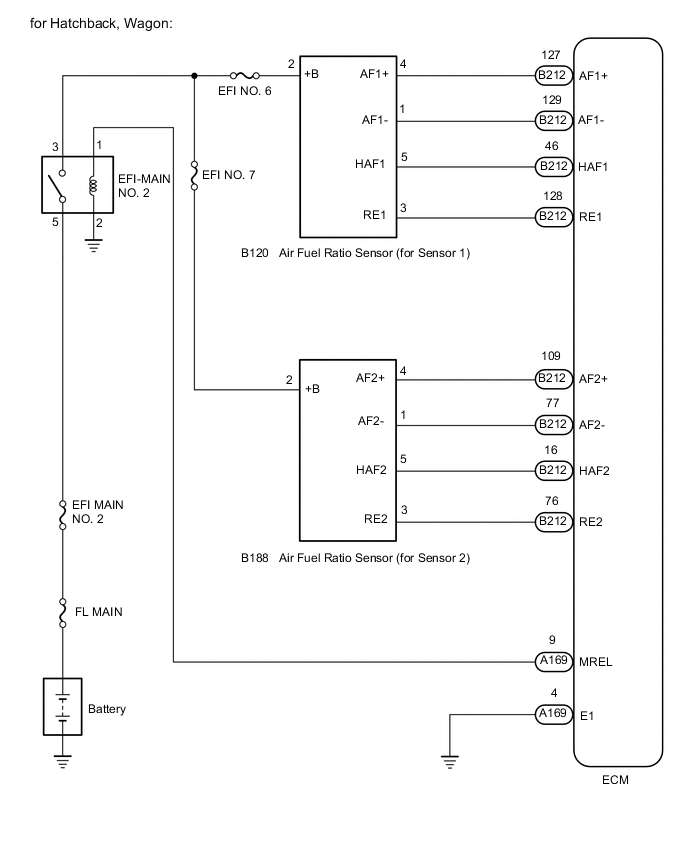
In order to capture carbon monoxide (CO), hydrocarbons (HC) and nitrogen oxides (NOx), and obtain a high collection/oxidization rate for particulate matter (PM) in the exhaust gas, an NSR + DPF catalytic converter is used. The air fuel ratio sensor (bank 1 sensor 1) is used to compensate for variation in the EGR rate to reduce PM accumulation of the DPF catalytic converter. Also, the air fuel ratio sensor (bank 1 sensor 1) and (bank 1 sensor 2) are used to control NOx reduction by the NSR.
The air fuel ratio sensor provides an output voltage that is proportional to the air fuel ratio that it is measuring. The air fuel ratio sensor output voltage is used for purposes such as feedback to allow the ECM to control the air fuel ratio mixture. The inner surface of the air fuel ratio sensor element is exposed to outside air. The outer surface of the sensor element is exposed to exhaust gases. The sensor element is made of platinum coated zirconia and includes an integrated heating element. The zirconia element generates a small voltage when there is a large difference in the oxygen concentrations of the exhaust and the outside air. The platinum coating amplifies the voltage generation. When heated, the sensor becomes very efficient. If the temperature of the exhaust is low, the sensor will not generate useful voltage signals without supplemental heating. The ECM regulates the supplemental heating by using a duty-cycle approach to regulate the average current in the heater element.
| DTC No. | Detection Item | DTC Detection Condition | Trouble Area | MIL | Memory |
|---|---|---|---|---|---|
| P0031 | Oxygen (A/F) Sensor Heater Control Circuit Low (Bank 1 Sensor 1) | Short to ground or open in air fuel ratio sensor (bank 1 sensor 1) heater circuit for 1 seconds or more (2 trip detection logic) |
|
Comes on | DTC stored |
| P0032 | Oxygen (A/F) Sensor Heater Control Circuit High (Bank 1 Sensor 1) | Short to +B in air fuel ratio sensor (bank 1 sensor 1) heater circuit for 1 seconds or more (2 trip detection logic) |
|
Comes on | DTC stored |
| P0037 | Oxygen Sensor Heater Control Circuit Low (Bank 1 Sensor 2) | Short to ground or open in air fuel ratio sensor (bank 1 sensor 2) heater circuit for 1 seconds or more (2 trip detection logic) |
|
Comes on | DTC stored |
| P0038 | Oxygen Sensor Heater Control Circuit High (Bank 1 Sensor 2) | Short to +B in air fuel ratio sensor (bank 1 sensor 2) heater circuit for 1 seconds or more (2 trip detection logic) |
|
Comes on | DTC stored |
| DTC No. | DTC Detection Drive Pattern |
|---|---|
| P0031 | 5 minutes elapse after engine coolant temperature reaches higher than 70°C (158°F) |
| P0032 | |
| P0037 | |
| P0038 |
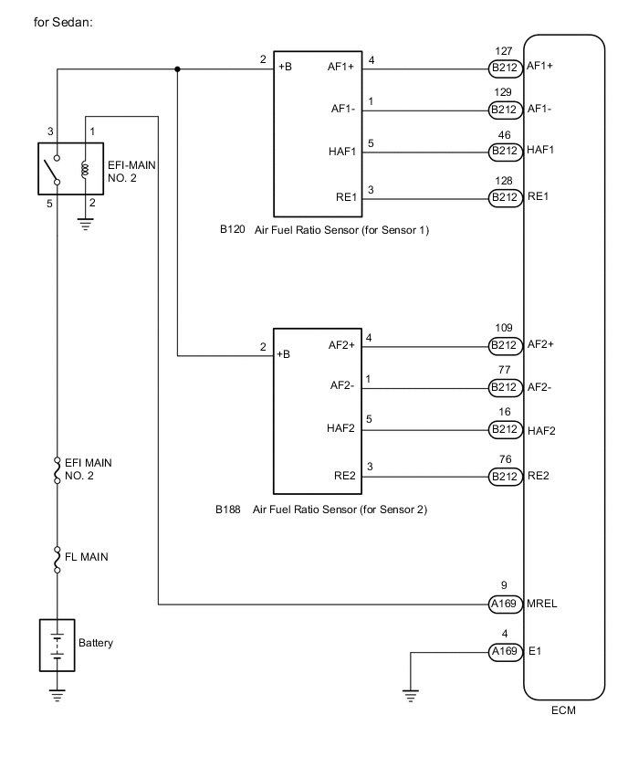
WIRING DIAGRAM
CAUTION / NOTICE / HINT
Note
-
When replacing the ECM and/or air fuel ratio sensor, perform ECM Initialization and Registration.
-
Inspect the fuses for circuits related to this system before performing the following procedure.
Tech Tips
-
When the ECM must be replaced, before replacing the ECM, perform the "Learning Values Save" function using the GTS. Then after installing a new ECM, perform all of the initialization and registration procedures for the "Learning Values Write" function by following the instructions shown on the GTS display.
-
Read freeze frame data using the GTS. Freeze frame data records the engine condition when malfunctions are detected. When troubleshooting, freeze frame data can help determine if the vehicle was moving or stationary, if the engine was warmed up or not, and other data from the time the malfunction occurred.
PROCEDURE
-
INSPECT AIR FUEL RATIO SENSOR (HEATER RESISTANCE)
-
Inspect the air fuel ratio sensor.
Tech Tips
-
For the air fuel ratio sensor (bank 1 sensor 1) inspection, refer to the following procedures.
-
For the air fuel ratio sensor (bank 1 sensor 2) inspection, refer to the following procedures.
Result Proceed to OK NG -
NG 
REPLACE AIR FUEL RATIO SENSOR Click here
OK 
-
-
CHECK TERMINAL VOLTAGE (POWER SOURCE OF AIR FUEL RATIO SENSOR)
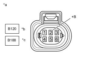
*a Front view of wire harness connector
(to Air Fuel Ratio Sensor)
*b for Bank 1 Senor 1 *c for Bank 1 Senor 2
-
for bank 1 sensor 1
-
Disconnect the air fuel ratio sensor (bank 1 sensor 1) connector.
-
Turn the ignition switch to ON.
-
Measure the voltage according to the value(s) in the table below.
Standard Voltage Tester Connection Condition Specified Condition B120-2 (+B) - Body ground Ignition switch ON 11 to 14 V
-
-
for bank 1 sensor 2
-
Disconnect the air fuel ratio sensor (bank 1 sensor 2) connector.
-
Turn the ignition switch to ON.
-
Measure the voltage according to the value(s) in the table below.
Standard Voltage Tester Connection Condition Specified Condition B188-2 (+B) - Body ground Ignition switch ON 11 to 14 V
Result Proceed to OK NG -
NG
CHECK HARNESS AND CONNECTOR (EFI-MAIN NO. 2 RELAY - AIR FUEL RATIO SENSOR) Click here
OK
-
-
CHECK HARNESS AND CONNECTOR (AIR FUEL RATIO SENSOR - ECM)
-
for bank 1 sensor 1
-
Disconnect the air fuel ratio sensor (bank 1 sensor 1) connector.
-
Disconnect the ECM connector.
-
Measure the resistance according to the value(s) in the table below.
Standard Resistance Tester Connection Condition Specified Condition B120-5 (HAF1) - B212-46 (HAF1) Always Below 1 Ω B120-5 (HAF1) or B212-46 (HAF1) - Body ground and other terminals Always 10 kΩ or higher
-
-
for bank 1 sensor 2
-
Disconnect the air fuel ratio sensor (bank 1 sensor 2) connector.
-
Disconnect the ECM connector.
-
Measure the resistance according to the value(s) in the table below.
Standard Resistance Tester Connection Condition Specified Condition B188-5 (HAF2) - B212-16 (HAF2) Always Below 1 Ω B188-5 (HAF2) or B212-16 (HAF2) - Body ground and other terminals Always 10 kΩ or higher
Result Proceed to OK NG -
NG
GO TO STEP 7 Click here
OK
-
-
REPLACE ECM
-
Replace the ECM.
Result Proceed to NEXT
NEXT
GO TO STEP 9 Click here
-
-
CHECK HARNESS AND CONNECTOR (EFI-MAIN NO. 2 RELAY - AIR FUEL RATIO SENSOR)
-
for bank 1 sensor 1
-
Remove the EFI-MAIN NO. 2 relay from the engine room relay block and junction block assembly.
-
Disconnect the air fuel ratio sensor (bank 1 sensor 1) connector.
-
Measure the resistance according to the value(s) in the table below.
Standard Resistance Tester Connection Condition Specified Condition EFI-MAIN NO. 2 relay terminal 3 - B120-2 (+B) Always Below 1 Ω EFI-MAIN NO. 2 relay terminal 3 or B120-2 (+B) - Body ground and other terminals Always 10 kΩ or higher
-
-
for bank 1 sensor 2
-
Remove the EFI-MAIN NO. 2 relay from the engine room relay block and junction block assembly.
-
Disconnect the air fuel ratio sensor (bank 1 sensor 2) connector.
-
Measure the resistance according to the value(s) in the table below.
Standard Resistance Tester Connection Condition Specified Condition EFI-MAIN NO. 2 relay terminal 3 - B188-2 (+B) Always Below 1 Ω EFI-MAIN NO. 2 relay terminal 3 or B188-2 (+B) - Body ground and other terminals Always 10 kΩ or higher
Result Proceed to OK NG -
NG
REPAIR OR REPLACE HARNESS OR CONNECTOR Click here
OK
-
-
CHECK ECM POWER SOURCE CIRCUIT
-
Check the ECM power source circuit and perform repairs as necessary.
Result Proceed to NEXT
NEXT
GO TO STEP 9 Click here
-
-
REPAIR OR REPLACE HARNESS OR CONNECTOR
Result Proceed to NEXT
NEXT
GO TO STEP 9 Click here
-
REPLACE AIR FUEL RATIO SENSOR
-
Replace the air fuel ratio sensor (bank 1 sensor 1).
-
Replace the air fuel ratio sensor (bank 1 sensor 2).
-
Perform A/F Sensor Compensation Reset.
Result Proceed to NEXT
NEXT
-
-
CONFIRM WHETHER MALFUNCTION HAS BEEN SUCCESSFULLY REPAIRED
-
Connect the GTS to the DLC3.
-
Turn the ignition switch to ON and turn the GTS on.
-
Clear the DTCs.
Powertrain > Engine and ECT > Clear DTCs -
Start the engine and allow it to idle until the engine coolant temperature reaches 70°C (158°F) or higher.
-
Allow the engine to idle for 5 minutes or more.
-
Enter the following menus: Powertrain / Engine and ECT / Trouble Codes / Pending.
-
Confirm that the pending DTC is not output again.
Powertrain > Engine and ECT > Trouble CodesResult Proceed to NEXT
NEXT 
END
-