СИСТЕМА ECD Injector Circuit
DESCRIPTION
The injector driver (EDU) drives the injector assemblies at high speeds with a high-voltage DC/DC converter. The ECM constantly monitors the injector driver (EDU) and stops the engine if an abnormal condition is detected.
CAUTION / NOTICE / HINT
Note
-
After replacing the ECM, the new ECM needs registration (Click here) and initialization Click here.
-
Inspect the fuses of circuits related to this system before performing the following procedure.
PROCEDURE
-
CHECK TERMINAL VOLTAGE (POWER SOURCE OF INJECTOR DRIVER (EDU))
Result Proceed to OK NG
-
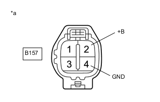
*a Front view of wire harness connector
(to Injector Driver (EDU))
Disconnect the injector driver (EDU) connector.
-
Turn the ignition switch to ON.
-
Measure the voltage according to the value(s) in the table below.
Standard Voltage Tester Connection Condition Specified Condition B157-2 (+B) - B157-4 (GND) Ignition switch ON 11 to 14 V Result Proceed to OK NG
OK 
REPLACE INJECTOR DRIVER (EDU) Click here
NG 
-
-
CHECK HARNESS AND CONNECTOR (INJECTOR DRIVER (EDU) - BODY GROUND)
-
Disconnect the injector driver (EDU) connector.
-
Measure the resistance according to the value(s) in the table below.
Standard Resistance Tester Connection Condition Specified Condition B157-4 (GND) - Body ground Always Below 1 Ω Result Proceed to OK NG
NG
REPAIR OR REPLACE HARNESS OR CONNECTOR
OK
-
-
INSPECT EDU RELAY
-
Inspect the EDU relay.
Result Proceed to OK NG
NG
REPLACE EDU RELAY
OK
-
-
CHECK TERMINAL VOLTAGE (POWER SOURCE OF EDU RELAY)
-
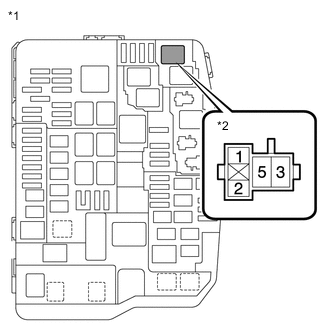
*1 Engine Room Relay Block and Junction Block Assembly *2 EDU Relay Remove the EDU relay from the engine room relay block and junction block assembly.
-
Measure the voltage according to the value(s) in the table below.
Standard Voltage Tester Connection Condition Specified Condition 5 (EDU relay) - Body ground Always 11 to 14 V Result Proceed to OK NG
NG
REPAIR OR REPLACE HARNESS OR CONNECTOR (BATTERY - EDU RELAY)
OK
-
-
CHECK HARNESS AND CONNECTOR (INJECTOR DRIVER (EDU) - EDU RELAY)
-
Disconnect the injector driver (EDU) connector.
-
Remove the EDU relay from the engine room relay block and junction block assembly.
-
Measure the resistance according to the value(s) in the table below.
Standard Resistance Tester Connection Condition Specified Condition B157-2 (+B) - 3 (EDU relay) Always Below 1 Ω B157-2 (+B) or 3 (EDU relay) - Body ground Always 10 kΩ or higher Result Proceed to OK NG
NG
REPAIR OR REPLACE HARNESS OR CONNECTOR
OK
-
-
CHECK HARNESS AND CONNECTOR (ECM - EDU RELAY)
-
Disconnect the ECM connector.
-
Remove the EDU relay from the engine room relay block and junction block assembly.
-
Measure the resistance according to the value(s) in the table below.
Standard Resistance Tester Connection Condition Specified Condition A118-44 (IREL) - 1 (EDU relay) Always Below 1 Ω A118-44 (IREL) or 1 (EDU relay) - Body ground Always 10 kΩ or higher Result Proceed to OK NG
NG
REPAIR OR REPLACE HARNESS OR CONNECTOR
OK
-
-
CHECK HARNESS AND CONNECTOR (EDU RELAY - EFI MAIN NO. 2 RELAY)
-
Remove the EDU relay and EFI MAIN NO. 2 relay from the engine room relay block and junction block assembly.
-
Measure the resistance according to the value(s) in the table below.
Standard Resistance Tester Connection Condition Specified Condition 2 (EDU relay) - 3 (EFI MAIN NO. 2 relay) Always Below 1 Ω 2 (EDU relay) or 3 (EFI MAIN NO. 2 relay) - Body ground Always 10 kΩ or higher Result Proceed to OK NG
NG
REPAIR OR REPLACE HARNESS OR CONNECTOR
OK
-
-
INSPECT EFI MAIN NO. 2 RELAY
-
Inspect the EFI MAIN NO. 2 relay.
Result Proceed to OK NG
NG
REPLACE EFI MAIN NO. 2 RELAY
OK
-
-
CHECK TERMINAL VOLTAGE (POWER SOURCE OF EFI MAIN NO. 2 RELAY)
-
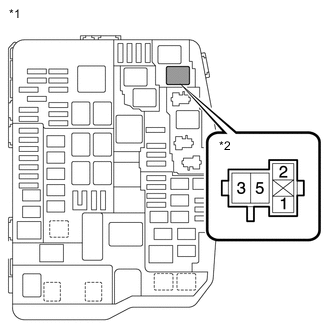
*1 Engine Room Relay Block and Junction Block Assembly *2 EFI MAIN NO. 2 Relay Remove the EFI MAIN NO. 2 relay from the engine room relay block and junction block assembly.
-
Measure the voltage according to the value(s) in the table below.
Standard Voltage Tester Connection Condition Specified Condition 5 (EFI MAIN NO. 2 relay) - Body ground Always 11 to 14 V Result Proceed to OK NG
NG
REPAIR OR REPLACE HARNESS OR CONNECTOR (BATTERY - EFI MAIN NO. 2 RELAY)
OK
-
-
CHECK HARNESS AND CONNECTOR (EFI MAIN NO. 2 - BODY GROUND)
-
Remove the EFI MAIN NO. 2 relay from the engine room relay block and junction block assembly.
-
Measure the resistance according to the value(s) in the table below.
Standard Resistance Tester Connection Condition Specified Condition 2 (EFI MAIN NO. 2 relay) - Body ground Always Below 1 Ω Result Proceed to OK NG
NG
REPAIR OR REPLACE HARNESS OR CONNECTOR
OK
-
-
CHECK HARNESS AND CONNECTOR (ECM - EFI MAIN NO. 2 RELAY)
-
Disconnect the ECM connector.
-
Remove the EFI MAIN NO. 2 relay from the engine room relay block and junction block assembly.
-
Measure the resistance according to the value(s) in the table below.
Standard Resistance Tester Connection Condition Specified Condition A118-45 (MREL) - 1 (EFI MAIN NO. 2 relay) Always Below 1 Ω A118-45 (MREL) or 1 (EFI MAIN NO. 2 relay) - Body ground Always 10 kΩ or higher Result Proceed to OK NG
OK
REPLACE ECM Click here
NG
REPAIR OR REPLACE HARNESS OR CONNECTOR
-