СИСТЕМА МЕХАНИЧЕСКОЙ ТРАНСМИССИИ "MULTIMODE" Pattern Select Switch Circuit
DESCRIPTION
While the vehicle is driven with the shift lever in E, the most appropriate gear is automatically selected according to the accelerator pedal opening angle and vehicle speed. During this time, shift control can be switched between easy (E) mode and easy sports (Es) mode by pressing the Es mode switch (combination switch assembly).
WIRING DIAGRAM
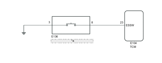
| *a | Es Mode Switch (Combination Switch Assembly) |
PROCEDURE
-
INSPECT COMBINATION SWITCH ASSEMBLY
-
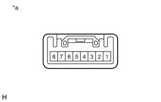
*a Component without harness connected
(Es Mode Switch (Combination Switch Assembly))
Remove the Es mode switch (combination switch assembly).
-
Measure the resistance according to the value(s) in the table below.
Standard Resistance Tester Connection Condition Specified Condition 8 - 3 Switch being pushed Below 50 Ω 8 - 3 Switch not being pushed 10 kΩ or higher Result Proceed to OK NG
NG 
REPLACE COMBINATION SWITCH ASSEMBLY Click here
OK 
-
-
CHECK HARNESS AND CONNECTOR (COMBINATION SWITCH ASSEMBLY - BODY GROUND)
-
Measure the resistance according to the value(s) in the table below.
Standard Resistance Tester Connection Condition Specified Condition E136-3 - Body ground Always Below 1 Ω Result Proceed to OK NG
NG
REPAIR OR REPLACE HARNESS OR CONNECTOR
OK
-
-
CHECK HARNESS AND CONNECTOR (COMBINATION SWITCH ASSEMBLY - TCM)
-
Disconnect the E104 TCM connector.
-
Measure the resistance according to the value(s) in the table below.
Standard Resistance Tester Connection Condition Specified Condition E104-23 (ESSW) - E136-8 Always Below 1 Ω E104-23 (ESSW) or E136-8 - Body ground Always 10 kΩ or higher Result Proceed to OK NG
NG
REPAIR OR REPLACE HARNESS OR CONNECTOR
OK
-
-
REPLACE TCM
-
Replace the TCM.
Result Proceed to NEXT
NEXT
PERFORM INITIALIZATION Click here
-