СИСТЕМА МЕХАНИЧЕСКОЙ ТРАНСМИССИИ "MULTIMODE", Diagnostic DTC:U0100
| DTC Code | DTC Name |
|---|---|
| U0100 | Lost Communication with ECM / PCM "A" |
DESCRIPTION
The TCM and ECM perform 2-way communication with each other via the Controller Area Network (CAN). The TCM sends signals to the ECM concerning required engine rpm, required engine torques, warning indicators in the combination meter, DTCs and other data. The ECM sends signals to the TCM concerning engine rpm, opening angles of the throttle valve, temperature of intake air, temperature of engine coolant, engine torques and other data. If the TCM cannot communicate with the ECM, the TCM will conclude that there is a malfunction in the CAN system, illuminate the MIL and multi-mode manual transaxle warning light, and store this DTC.
| DTC No. | Detection Item | DTC Detection Condition | Trouble Area | MIL | Warning Indicate | Memory |
|---|---|---|---|---|---|---|
| U0100 | Lost Communication with ECM / PCM "A" | No communication with the ECM (1-trip detection logic) |
|
Comes on | Comes on | DTC stored |
WIRING DIAGRAM
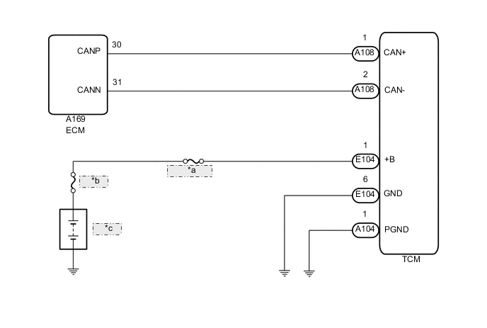
| *a | ECU-B NO. 2 |
| *b | FL MAIN |
| *c | Battery |
CAUTION / NOTICE / HINT
Tech Tips
If the CAN communication malfunctions, the TCM cannot receive the current data from the ECM. In this case, the freeze frame data output from the TCM has not been updated, so it will not be useful information for the inspection procedure. However, reading the Data List as the first step of troubleshooting is effective to find malfunctions.
Note
-
Inspect the fuses for circuits related to this system before performing the following procedure.
-
In the table below, the values listed under Normal Condition are for reference only. Do not depend solely on these reference values when deciding whether a part is faulty or not.
-
DATA LIST
-
Warm up the engine.
-
Turn the ignition switch off.
-
Connect the GTS to the DLC3.
-
Turn the ignition switch to ON.
-
Turn the GTS on.
-
Enter the following menus: Powertrain / Multi-Mode M/T / Data List.
Powertrain > Multi-Mode M/T > Data ListTester Display Measurement Item Range Normal Condition Diagnostic Note Calculated Engine Load Load calculated by ECM Min.: 0%, Max.: 100% 10 to 25%: Idling
5 to 20%: Running without load (2500 rpm)
- Engine Coolant Temperature Coolant temperature Min.: -40°C, Max.: 140°C 75 to 95°C (167 to 203°F):
After engine warmed up
-
If value -40°C (-40°F): sensor circuit open
-
If value 140°C (284°F): sensor circuit shorted
Backup Engine Speed Back-up engine speed Min.: 0 rpm, Max.: 8160 rpm 0 rpm: Engine stopped
720 to 820 rpm: Idling
0 rpm displayed when malfunctions in CAN communication Accelerator Pedal Angle Accelerator pedal angle Min.: 0%, Max.: 100% 0%: Accelerator pedal released 0 % displayed when malfunctions in CAN communication regardless of the accelerator pedal status.
Powertrain > Multi-Mode M/T > Data ListTester Display Calculated Engine Load Engine Coolant Temperature Backup Engine Speed Accelerator Pedal Angle -
-
PROCEDURE
-
CHECK TCM (+B AND GND TERMINALS)
-
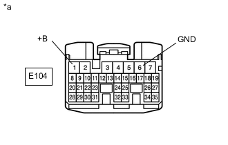
*a Front view of wire harness connector
(to TCM)
Disconnect the TCM connector.
-
Measure the voltage according to the value(s) in the table below.
Standard Voltage Tester Connection Condition Specified Condition E104-1 (+B) - E104-6 (GND) Always 11 to 14 V Result Proceed to OK NG
NG 
CHECK HARNESS AND CONNECTOR (TCM - BODY GROUND) Click here
OK 
-
-
CHECK HARNESS AND CONNECTOR (TCM - ECM)
-
Disconnect the ECM connector.
-
Measure the resistance according to the value(s) in the table below.
Standard Resistance Tester Connection Condition Specified Condition A169-30 (CANP) - A108-1 (CAN+) Always Below 1 Ω A169-31 (CANN) - A108-2 (CAN-) Always Below 1 Ω A169-30 (CANP) or A108-1 (CAN+) - Body ground Always 10 kΩ or higher A169-31 (CANN) or A108-2 (CAN-) - Body ground Always 10 kΩ or higher Result Proceed to OK NG
NG 
REPAIR OR REPLACE HARNESS OR CONNECTOR
OK
-
-
REPLACE ECM
-
Replace the ECM.
CAUTION:
Replace the ECM with a known good ECM of the same model vehicle.
Result Proceed to NEXT
NEXT
-
-
CHECK IF DTC RECURS
-
Connect the GTS to the DLC3.
-
Turn the ignition switch to ON.
-
Turn the GTS on.
-
Clear the DTCs.
Powertrain > Engine and ECT > Clear DTCs -
Enter the following menus: Powertrain / Engine and ECT / Trouble Codes.
Powertrain > Engine and ECT > Trouble Codes -
Read the DTCs.
Result Result Proceed to DTC U0101 is output A DTCs are not output B
B
END
A
-
-
REPLACE TCM
-
Replace the TCM.
Result Proceed to NEXT
NEXT
PERFORM INITIALIZATION Click here
-
-
CHECK HARNESS AND CONNECTOR (TCM - BODY GROUND)
-
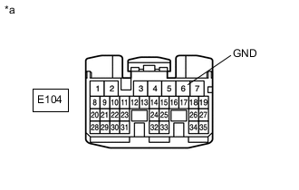
*a Front view of wire harness connector
(to TCM)
Measure the resistance according to the value(s) in the table below.
Standard Resistance Tester Connection Condition Specified Condition E104-6 (GND) - Body ground Always Below 1 Ω Result Proceed to OK NG
OK
REPAIR OR REPLACE HARNESS OR CONNECTOR (TCM - BATTERY)
NG
REPAIR OR REPLACE HARNESS OR CONNECTOR
-