CENTER AIRBAG SENSOR ASSEMBLY (for TMC, TMMR Made) INSTALLATION

-
INSTALL AIRBAG SENSOR ASSEMBLY
-
Check that the ignition switch is off.
-
Check that the cable is disconnected from the negative (-) battery terminal.
CAUTION:
Wait at least 90 seconds after disconnecting the cable from the negative (-) battery terminal to disable the SRS system.
-
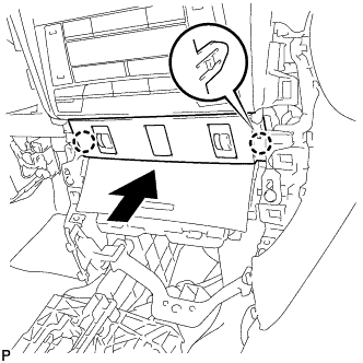
Using SST, install the airbag sensor assembly with the 3 bolts.
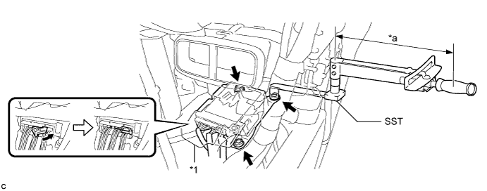
- SST
- 09961-00950
Text in Illustration *1 Waterproof Sheet - - *a Torque Wrench Fulcrum Length - - - Torque:
- Specified tightening torque
- 18 N*m { 178 kgf*cm, 13 ft.*lbf }
Note
-
This torque value is effective when SST is parallel to a torque wrench.
-
If the airbag sensor assembly has been dropped, or there are any cracks, dents or other defects in the case or connector, replace it with a new one.
-
When installing the airbag sensor assembly, be careful that the SRS wiring does not interfere with or is not pinched between other parts.
-
When the ignition switch is first turned on (IG) after the airbag sensor assembly has been replaced, make sure that no one is in the vehicle.
-
Calculate the torque wrench reading when changing the fulcrum length of the torque wrench Click here.
-
When using SST (fulcrum length of 150 mm (5.91 in.)) + torque wrench (fulcrum length of 250 mm (9.84 in.)): 11 N*m (112 kgf*cm, 8 ft.*lbf)
-
Connect the connectors to the airbag sensor assembly as shown in the illustration.
Note
When connecting any airbag connector, take care not to damage the airbag wire harness.
-
Check that the waterproof sheet is properly set.
-
Check that there is no looseness in the installation parts of the airbag sensor assembly.
-
-
INSTALL NO. 1 CONSOLE BOX DUCT
-
Install the No. 1 console box duct with the clip.
-
-
INSTALL FLOOR CARPET BRACKET LH
-
Engage the 2 guides.
-
Install the floor carpet bracket LH with the 2 clips.
-
-
INSTALL FLOOR CARPET BRACKET RH
-
Engage the 2 guides.
-
Install the floor carpet bracket RH with the 2 clips.
-
-
INSTALL FRONT NO. 2 CONSOLE BOX INSERT
-
Engage the clip and 4 guides as shown in the illustration.
-
Install the front No. 2 console box insert with the 2 screws <D>.
-
for LHD:
-
Engage the 2 claws to connect the room temperature sensor.
-
-
-
INSTALL CONSOLE BOX INSERT
-
Engage the clip and 4 guides as shown in the illustration.
-
Install the console box insert with the 2 screws <D>.
-
for RHD:
-
Engage the 2 claws to connect the room temperature sensor.
-
-
-
INSTALL LOWER INSTRUMENT PANEL SUB-ASSEMBLY
-
Engage the 2 clips and 4 guides.
-
Install the 3 screws <D>.
-
Close the lower instrument panel door.
-
Install the lower instrument panel sub-assembly with the bolt <B> and screws <D>.
-
-
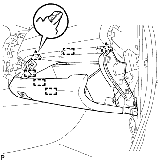
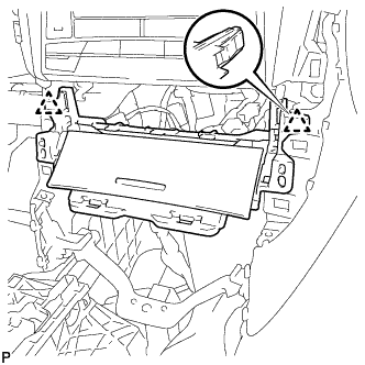
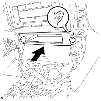
INSTALL NO. 2 INSTRUMENT PANEL UNDER COVER SUB-ASSEMBLY
-
Connect the connector.
-
Engage the 2 guides and 4 claws to install the No. 2 instrument panel under cover sub-assembly.
-
-
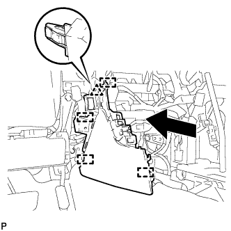
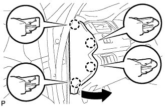
INSTALL INSTRUMENT SIDE PANEL RH
-
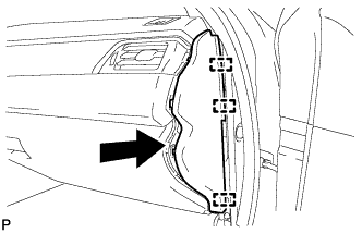
Engage the 3 guides as shown in the illustration.
-
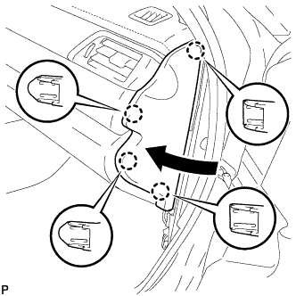
Engage the 4 claws to install the instrument side panel RH as shown in the illustration.
-
-
INSTALL FRONT DOOR OPENING TRIM WEATHERSTRIP RH
-
INSTALL COWL SIDE TRIM SUB-ASSEMBLY RH
Tech Tips
Use the same procedure for the RH side and LH side Click here.
-
INSTALL FRONT DOOR SCUFF PLATE RH
Tech Tips
Use the same procedure for the RH side and LH side Click here.
-
INSTALL FRONT ASH RECEPTACLE ASSEMBLY
-
Connect each connector.
-
Engage the 2 clips.
-
Install the front ash receptacle assembly with the 2 screws <D>.
-
-
INSTALL FRONT CONSOLE UPPER PANEL GARNISH
-
for Blank Type:
-
Engage the 2 claws to install the front console upper panel garnish as shown in the illustration.
-
-
for 3 Switch Hole Type:
-
Connect each connector.
-
Engage the 2 claws to install the front console upper panel garnish as shown in the illustration.
-
-
-
INSTALL INSTRUMENT PANEL SUB-ASSEMBLY
-
w/o Driver Side Knee Airbag:
-
Engage the 5 clips and 3 guides.
-
-
w/ Driver Side Knee Airbag:
-
Engage the 4 claws, 7 clips and 3 guides.
-
-
Install the instrument panel sub-assembly with the 2 bolts <B>.
-
-
CONNECT HOOD LOCK CONTROL LEVER SUB-ASSEMBLY
-
Engage the claw and 2 guides to connect the hood lock control lever sub-assembly.
-
-
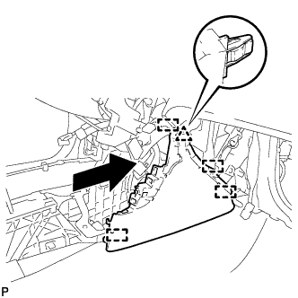
INSTALL INSTRUMENT SIDE PANEL LH
-
Engage the 3 guides.
-
Engage the 4 claws to install the instrument side panel LH as shown in the illustration.
-
-
INSTALL FRONT DOOR OPENING TRIM WEATHERSTRIP LH
-
INSTALL COWL SIDE TRIM SUB-ASSEMBLY LH
-
Engage the 2 clips.
-
Install the cowl side trim sub-assembly LH with the clip.
-
-
INSTALL FRONT DOOR SCUFF PLATE LH
-
Engage the 10 claws to install the front door scuff plate LH.
-
-
INSTALL CONSOLE BOX ASSEMBLY
-
CONNECT CABLE TO NEGATIVE BATTERY TERMINAL
Note
When disconnecting the cable, some systems need to be initialized after the cable is reconnected Click here.
-
PERFORM DIAGNOSTIC SYSTEM CHECK
-
INSPECT SRS WARNING LIGHT