ENGINE IMMOBILISER SYSTEM (w/o Smart Entry and Start System) Security Indicator Light Does not Blink
DESCRIPTION
-
The transponder key ECU assembly blinks the security indicator light when the immobiliser is set (no key is in the ignition key cylinder).
-
The main body ECU (multiplex network body ECU) blinks the security indicator light when the theft deterrent system is in the arming preparation state or alarm sounding state.
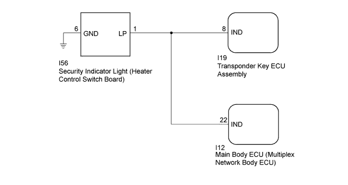
WIRING DIAGRAM
INSPECTION PROCEDURE
Note
If the transponder key ECU assembly is replaced, refer to Service Bulletin.
PROCEDURE
-
PERFORM ACTIVE TEST USING INTELLIGENT TESTER (SECURITY INDICATOR LIGHT)
-
Connect the intelligent tester to the DLC3.
-
Turn the ignition switch to ON.
-
Turn the intelligent tester on.
-
Enter the following menus: Body / Immobiliser or Main Body / Active Test.
-
Perform the Active Test according to the display on the intelligent tester.
Immobiliser (Transponder Key ECU Assembly) Tester Display Test Part Control Range Diagnostic Note Security Indicator Security indicator light ON/OFF - Main Body (Main Body ECU (Multiplex Network Body ECU)) Tester Display Test Part Control Range Diagnostic Note Security Indicator Security indicator light ON/OFF - Result Result Proceed to Security indicator light operation is normal when performing the "Main Body" and "Immobiliser" Active Test A
-
Security indicator light operation is not normal when performing the "Immobiliser" Active Test
-
Security indicator light operation is normal when performing the "Main Body" Active Test
B
-
Security indicator light operation is normal when performing the "Immobiliser" Active Test
-
Security indicator light operation is not normal when performing the "Main Body" Active Test
C Security indicator light operation is not normal when performing the "Main Body" and "Immobiliser" Active Test D -
B 
CHECK HARNESS AND CONNECTOR (SECURITY INDICATOR LIGHT (HEATER CONTROL SWITCH BOARD) - TRANSPONDER KEY ECU ASSEMBLY) Click here
C
CHECK HARNESS AND CONNECTOR (SECURITY INDICATOR LIGHT (HEATER CONTROL SWITCH BOARD) - MAIN BODY ECU (MULTIPLEX NETWORK BODY ECU)) Click here
D
CHECK HARNESS AND CONNECTOR Click here
A 
-
-
CHECK SECURITY INDICATOR LIGHT OPERATION
-
When the immobiliser is set, check that the security indicator light blinks.*1
OK The security indicator light blinks normally. -
When the theft deterrent system is in the arming preparation state, check that the security indicator light on Click here.*2
OK The security indicator light is on normally. Result Result Proceed to Both *1 and *2 are OK A *1 is NG (*2 is OK) B *2 is NG (*1 is OK) C Both *1 and *2 are NG D
B 
REPLACE TRANSPONDER KEY ECU ASSEMBLY
C
REPLACE MAIN BODY ECU (MULTIPLEX NETWORK BODY ECU) Click here
D
REPLACE SECURITY INDICATOR LIGHT (HEATER CONTROL SWITCH BOARD) Click here
A 
USE SIMULATION METHOD TO CHECK Click here
-
-
CHECK HARNESS AND CONNECTOR (SECURITY INDICATOR LIGHT (HEATER CONTROL SWITCH BOARD) - TRANSPONDER KEY ECU ASSEMBLY)
-
Disconnect the security indicator light (heater control switch board) connector.
-
Disconnect the transponder key ECU assembly connector.
-
Measure the resistance according to the value(s) in the table below.
Standard Resistance Tester Connection Condition Specified Condition I19-8 (IND) - I56-1 (LP) Always Below 1 Ω I19-8 (IND) - Body ground Always 10 kΩ or higher
NG
REPAIR OR REPLACE HARNESS OR CONNECTOR
OK
REPLACE TRANSPONDER KEY ECU ASSEMBLY
-
-
CHECK HARNESS AND CONNECTOR (SECURITY INDICATOR LIGHT (HEATER CONTROL SWITCH BOARD) - MAIN BODY ECU (MULTIPLEX NETWORK BODY ECU))
-
Disconnect the security indicator light (heater control switch board) connector.
-
Disconnect the main body ECU (multiplex network body ECU) connector.
-
Measure the resistance according to the value(s) in the table below.
Standard Resistance Tester Connection Condition Specified Condition I12-22 (IND) - I56-1 (LP) Always Below 1 Ω I12-22 (IND) - Body ground Always 10 kΩ or higher
NG
REPAIR OR REPLACE HARNESS OR CONNECTOR
OK
REPLACE MAIN BODY ECU (MULTIPLEX NETWORK BODY ECU) Click here
-
-
CHECK HARNESS AND CONNECTOR
-
Disconnect the security indicator light (heater control switch board) connector.
-
Disconnect transponder key ECU assembly connector.
-
Disconnect the main body ECU (multiplex network body ECU) connector.
-
Measure the resistance according to the value(s) in the table below.
Standard Resistance Tester Connection Condition Specified Condition I19-8 (IND) - I56-1 (LP) Always Below 1 Ω I12-22 (IND) - I56-1 (LP) Always Below 1 Ω I56-1 (LP) - Body ground Always 10 kΩ or higher I56-6 (GND) - Body ground Always Below 1 Ω
NG
REPAIR OR REPLACE HARNESS OR CONNECTOR
OK
-
-
REPLACE SECURITY INDICATOR LIGHT (HEATER CONTROL SWITCH BOARD)
-
Temporarily replace the security indicator light (heater control switch board) with a new or known good one Click here.
-
When the immobiliser is set or theft deterrent system is in the arming preparation state, check that the security indicator light blinks.
OK Security indicator light blinks.
NG
REPLACE TRANSPONDER KEY ECU ASSEMBLY Click here
OK
END (HEATER CONTROL SWITCH BOARD WAS DEFECTIVE)
-
-
REPLACE TRANSPONDER KEY ECU ASSEMBLY
-
Temporarily replace the transponder key ECU assembly with a new or known good one.
Tech Tips
Refer to Service Bulletin.
-
When the immobiliser is set or theft deterrent system is in the arming preparation state, check that the security indicator light blinks.
OK Security indicator light blinks.
NG
REPLACE MAIN BODY ECU (MULTIPLEX NETWORK BODY ECU) Click here
OK
END (TRANSPONDER KEY ECU ASSEMBLY WAS DEFECTIVE)
-