NAVIGATION SYSTEM (for Radio and Display Type), Diagnostic DTC:B15C0, B15C1
| DTC Code | DTC Name |
|---|---|
| B15C0 | Short in GPS Antenna |
| B15C1 | Open in GPS Antenna |
DESCRIPTION
These DTCs are stored when a malfunction occurs in the navigation antenna assembly.
| DTC No. | DTC Detection Condition | Trouble Area |
|---|---|---|
| B15C0 | Navigation antenna malfunction |
|
| B15C1 | Navigation antenna power source malfunction |
-
*: w/ Heated Windshield Defroster System
INSPECTION PROCEDURE
Note
Check that the navigation antenna assembly cable is properly installed and does not have any sharp bends, pinching or loose connections before performing the following inspection procedure Click here.
PROCEDURE
-
CHECK DTC
-
Clear the DTCs Click here.
-
Recheck for DTCs and check that no DTCs are output.
OK No DTCs are output.
NG 
CHECK MODEL Click here
OK 
USE SIMULATION METHOD TO CHECK Click here
-
-
CHECK MODEL
-
Choose the model to be inspected.
Result Result Proceed to w/ Heated Windshield Defroster System A w/o Heated Windshield Defroster System B
B
INSPECT NAVIGATION ANTENNA ASSEMBLY Click here
A 
-
-
CHECK ANTENNA CORD SUB-ASSEMBLY
-
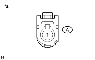
Text in Illustration *a Antenna cord sub-assembly connector
(to Radio and Display Receiver Assembly)
Disconnect the antenna cord sub-assembly connector from the radio and display receiver assembly.
-
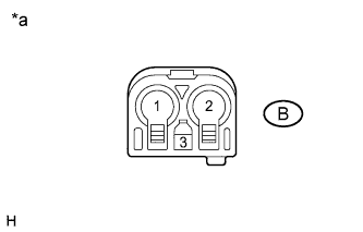
Text in Illustration *a Antenna cord sub-assembly connector
(to No. 2 Antenna Cord Sub-assembly)
Disconnect the antenna cord sub-assembly connector from the No. 2 antenna cord sub-assembly.
-
Measure the resistance according to the value(s) in the table below.
Standard Resistance Tester Connection Condition Specified Condition A-1 - B-1 Always Below 1 Ω A-1 - Body ground Always 10 kΩ or higher
NG 
REPLACE ANTENNA CORD SUB-ASSEMBLY Click here
OK
-
-
CHECK NO. 2 ANTENNA CORD SUB-ASSEMBLY
-
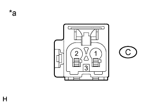
Text in Illustration *a No. 2 antenna cord sub-assembly connector
(to Antenna Cord Sub-assembly)
Disconnect the No. 2 antenna cord sub-assembly connector from the antenna cord sub-assembly.
-

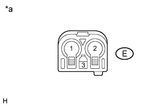
Text in Illustration *a No. 2 antenna cord sub-assembly connector
(to Wire Harness)
Disconnect the No. 2 antenna cord sub-assembly connector from wire harness.
-
Measure the resistance according to the value(s) in the table below.
Standard Resistance Tester Connection Condition Specified Condition C-1 - D-2 Always Below 1 Ω C-1 - Body ground Always 10 kΩ or higher
NG
REPLACE NO. 2 ANTENNA CORD SUB-ASSEMBLY Click here
OK
-
-
CHECK HARNESS AND CONNECTOR (NAVIGATION ANTENNA ASSEMBLY - NO. 2 ANTENNA CORD SUB-ASSEMBLY)
-
Text in Illustration *a Front view of wire harness connector
(to No. 2 Antenna Cord Sub-assembly)
Disconnect the wire harness connector from the No. 2 antenna cord sub-assembly connector.
-
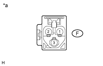
Text in Illustration *a Front view of wire harness connector
(to Navigation Antenna Assembly)
Disconnect the wire harness connector from the navigation antenna assembly.
-
Measure the resistance according to the value(s) in the table below.
Standard Resistance Tester Connection Condition Specified Condition E-2 - F-2 Always Below 1 Ω E-1 - Body ground Always 10 kΩ or higher
NG
REPAIR OR REPLACE HARNESS OR CONNECTOR
OK
-
-
INSPECT NAVIGATION ANTENNA ASSEMBLY
-
Remove the navigation antenna assembly Click here.
-
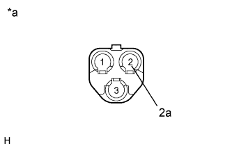
Text in Illustration *a Component without harness connected
(Navigation Antenna Assembly)
Measure the resistance according to the value(s) in the table below.
Standard Resistance Tester Connection Condition Specified Condition 2 - 2a Always 50 to 500 Ω
NG
REPLACE NAVIGATION ANTENNA ASSEMBLY Click here
OK
REPLACE NAVIGATION ANTENNA ASSEMBLY Click here
-
-
INSPECT NAVIGATION ANTENNA ASSEMBLY
-
Remove the navigation antenna assembly Click here.
-
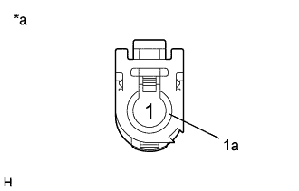
Text in Illustration *a Component without harness connected
(Navigation Antenna Assembly)
Measure the resistance according to the value(s) in the table below.
Standard Resistance Tester Connection Condition Specified Condition 1 - 1a Always 50 to 500 Ω
NG
REPLACE NAVIGATION ANTENNA ASSEMBLY Click here
OK
REPLACE RADIO AND DISPLAY RECEIVER ASSEMBLY Click here
-