AUDIO AND VISUAL SYSTEM (for Radio and Display Type) Microphone Circuit between Microphone and Radio Receiver
DESCRIPTION
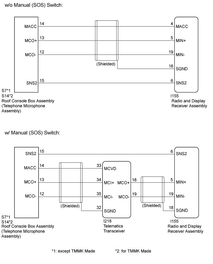
w/o Manual (SOS) Switch:The radio and display receiver assembly and roof console box assembly (telephone microphone assembly) are connected to each other using the microphone connection detection signal lines.
Using this circuit, the radio and display receiver assembly sends power to the roof console box assembly (telephone microphone assembly), and the roof console box assembly (telephone microphone assembly) sends microphone signals to the radio and display receiver assembly.
w/ Manual (SOS) Switch:The radio and display receiver assembly and roof console box assembly (telephone microphone assembly) are connected to each other using the microphone connection detection signal lines.
Using this circuit, the telematics transceiver sends power to the roof console box assembly (telephone microphone assembly), and the roof console box assembly (telephone microphone assembly) sends microphone signals to the radio and display receiver assembly via the telematics transceiver.
WIRING DIAGRAM
INSPECTION PROCEDURE
Note
Depending on the parts that are replaced during vehicle inspection or maintenance, performing initialization, registration or calibration may be needed. Refer to Precaution for Audio and Visual System (w/ Manual (SOS) Switch) Click here.
PROCEDURE
-
CHECK MICROPHONE (OPERATION CHECK)
-
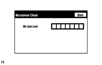
Enter the "Microphone Check" screen.
Refer to Check Microphone in Operation Check Click here.
-
When a voice is input into the microphone, check that the microphone input level meter changes according to the input voice.
OK Check result is normal.
NG 
CONFIRM MODEL Click here
OK 
PROCEED TO NEXT SUSPECTED AREA SHOWN IN PROBLEM SYMPTOMS TABLE Click here
-
-
CONFIRM MODEL
-
Choose the model to be inspected.
Result Model Proceed to w/o Manual (SOS) switch A w/ Manual (SOS) switch B
B
CHECK HARNESS AND CONNECTOR (RADIO AND DISPLAY RECEIVER ASSEMBLY - ROOF CONSOLE BOX ASSEMBLY (TELEPHONE MICROPHONE ASSEMBLY)) Click here
A 
-
-
CHECK HARNESS AND CONNECTOR (RADIO AND DISPLAY RECEIVER ASSEMBLY - ROOF CONSOLE BOX ASSEMBLY (TELEPHONE MICROPHONE ASSEMBLY))
-
Disconnect the I155 radio and display receiver assembly connector.
-
Disconnect the S7 roof console box assembly (telephone microphone assembly) connector*1.
-
Disconnect the S14 roof console box assembly (telephone microphone assembly) connector*2.
-
Measure the resistance according to the value(s) in the table below.
Standard Resistance Tester Connection Condition Specified Condition I155-4 (MACC) - S7-14 (MACC)*1 Always Below 1 Ω I155-4 (MACC) - S14-14 (MACC)*2 Always Below 1 Ω I155-5 (MIN+) - S7-13 (MCO+)*1 Always Below 1 Ω I155-5 (MIN+) - S14-13 (MCO+)*2 Always Below 1 Ω I155-19 (MIN-) - S7-12 (MCO-)*1 Always Below 1 Ω I155-19 (MIN-) - S14-12 (MCO-)*2 Always Below 1 Ω I155-6 (SNS2) - S7-15 (SNS2)*1 Always Below 1 Ω I155-6 (SNS2) - S14-15 (SNS2)*2 Always Below 1 Ω I155-4 (MACC) or S7-14 (MACC)*1 - Body ground Always 10 kΩ or higher I155-4 (MACC) or S14-14 (MACC)*2 - Body ground Always 10 kΩ or higher I155-5 (MIN+) or S7-13 (MCO+)*1 - Body ground Always 10 kΩ or higher I155-5 (MIN+) or S14-13 (MCO+)*2 - Body ground Always 10 kΩ or higher I155-19 (MIN-) or S7-12 (MCO-)*1 - Body ground Always 10 kΩ or higher I155-19 (MIN-) or S14-12 (MCO-)*2 - Body ground Always 10 kΩ or higher I155-18 (SGND) - Body ground Always 10 kΩ or higher I155-6 (SNS2) or S7-15 (SNS2)*1 - Body ground Always 10 kΩ or higher I155-6 (SNS2) or S14-15 (SNS2)*2 - Body ground Always 10 kΩ or higher
-
*1: except TMMK Made
-
*2: for TMMK Made
-
NG 
REPAIR OR REPLACE HARNESS OR CONNECTOR
OK
-
-
INSPECT RADIO AND DISPLAY RECEIVER ASSEMBLY
-
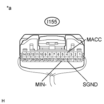
Text in Illustration *a Component with harness connected
(Radio and Display Receiver Assembly)
Measure the voltage according to the value(s) in the table below.
Standard Voltage Tester Connection Condition Specified Condition I155-4 (MACC) - Body ground Ignition switch ACC 4 to 6 V -
Measure the resistance according to the value(s) in the table below.
Standard Resistance Tester Connection Condition Specified Condition I155-18 (SGND) - Body ground Always Below 1 Ω I155-19 (MIN-) - Body ground Always Below 1 Ω Result Result Proceed to NG A OK B
B
INSPECT ROOF CONSOLE BOX ASSEMBLY (TELEPHONE MICROPHONE ASSEMBLY) Click here
A
REPLACE RADIO AND DISPLAY RECEIVER ASSEMBLY Click here
-
-
CHECK HARNESS AND CONNECTOR (RADIO AND DISPLAY RECEIVER ASSEMBLY - ROOF CONSOLE BOX ASSEMBLY (TELEPHONE MICROPHONE ASSEMBLY))
-
Disconnect the I155 radio and display receiver assembly connector.
-
Disconnect the S7 roof console box assembly (telephone microphone assembly) connector*1.
-
Disconnect the S14 roof console box assembly (telephone microphone assembly) connector*2.
-
Measure the resistance according to the value(s) in the table below.
Standard Resistance Tester Connection Condition Specified Condition I155-6 (SNS2) - S7-15 (SNS2)*1 Always Below 1 Ω I155-6 (SNS2) - S14-15 (SNS2)*2 Always Below 1 Ω I155-6 (SNS2) or S7-15 (SNS2)*1 - Body ground Always 10 kΩ or higher I155-6 (SNS2) or S14-15 (SNS2)*2 - Body ground Always 10 kΩ or higher
-
*1: except TMMK Made
-
*2: for TMMK Made
-
NG
REPAIR OR REPLACE HARNESS OR CONNECTOR
OK
-
-
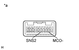
CHECK HARNESS AND CONNECTOR (RADIO AND DISPLAY RECEIVER ASSEMBLY - TELEMATICS TRANSCEIVER)
-
Disconnect the I155 radio and display receiver assembly connector.
-
Disconnect the I218 telematics transceiver connector.
-
Measure the resistance according to the value(s) in the table below.
Standard Resistance Tester Connection Condition Specified Condition I155-5 (MIN+) - I218-18 (MCO+) Always Below 1 Ω I155-19 (MIN-) - I218-19 (MCO-) Always Below 1 Ω I155-5 (MIN+) or I218-18 (MCO+) - Body ground Always 10 kΩ or higher I155-19 (MIN-) or I218-19 (MCO-) - Body ground Always 10 kΩ or higher I155-18 (SGND) - Body ground Always 10 kΩ or higher
NG
REPAIR OR REPLACE HARNESS OR CONNECTOR
OK
-
-
CHECK HARNESS AND CONNECTOR (TELEMATICS TRANSCEIVER - ROOF CONSOLE BOX ASSEMBLY (TELEPHONE MICROPHONE ASSEMBLY))
-
Disconnect the I218 telematics transceiver connector.
-
Disconnect the S7 roof console box assembly (telephone microphone assembly) connector*1.
-
Disconnect the S14 roof console box assembly (telephone microphone assembly) connector*2.
-
Measure the resistance according to the value(s) in the table below.
Standard Resistance Tester Connection Condition Specified Condition I218-33 (MCVD) - S7-14 (MACC)*1 Always Below 1 Ω I218-33 (MCVD) - S14-14 (MACC)*2 Always Below 1 Ω I218-34 (MCI+) - S7-13 (MCO+)*1 Always Below 1 Ω I218-34 (MCI+) - S14-13 (MCO+)*2 Always Below 1 Ω I218-35 (MCI-) - S7-12 (MCO-)*1 Always Below 1 Ω I218-35 (MCI-) - S14-12 (MCO-)*2 Always Below 1 Ω I218-33 (MCVD) or S7-14 (MACC)*1 - Body ground Always 10 kΩ or higher I218-33 (MCVD) or S14-14 (MACC)*2 - Body ground Always 10 kΩ or higher I218-34 (MCI+) or S7-13 (MCO+)*1 - Body ground Always 10 kΩ or higher I218-34 (MCI+) or S14-13 (MCO+)*2 - Body ground Always 10 kΩ or higher I218-35 (MCI-) or S7-12 (MCO-)*1 - Body ground Always 10 kΩ or higher I218-35 (MCI-) or S14-12 (MCO-)*2 - Body ground Always 10 kΩ or higher I218-32 (SGND) - Body ground Always 10 kΩ or higher
-
*1: except TMMK Made
-
*2: for TMMK Made
-
NG
REPAIR OR REPLACE HARNESS OR CONNECTOR
OK
-
-
INSPECT RADIO AND DISPLAY RECEIVER ASSEMBLY
-
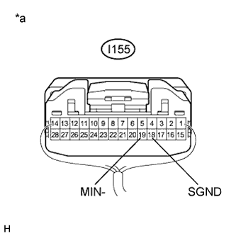
Text in Illustration *a Component with harness connected
(Radio and Display Receiver Assembly)
Disconnect the I218 telematics transceiver connector.
-
Measure the resistance according to the value(s) in the table below.
Standard Resistance Tester Connection Condition Specified Condition I155-18 (SGND) - Body ground Always Below 1 Ω I155-19 (MIN-) - Body ground Always Below 1 Ω -
Proceed to the next step based on the inspection result.
Result Result Proceed to OK A NG
(for TMMK Made)
B NG
(for TMC, TMMR Made)
C
B
REPLACE RADIO AND DISPLAY RECEIVER ASSEMBLY Click here
C
REPLACE RADIO AND DISPLAY RECEIVER ASSEMBLY Click here
A
-
-
INSPECT TELEMATICS TRANSCEIVER
-
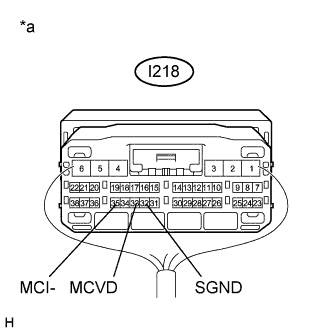
Text in Illustration *a Component with harness connected
(Telematics Transceiver)
Measure the voltage according to the value(s) in the table below.
Standard Voltage Tester Connection Condition Specified Condition I218-33 (MCVD) - Body ground Ignition switch ACC 4 to 6 V -
Measure the resistance according to the value(s) in the table below.
Standard Resistance Tester Connection Condition Specified Condition I218-35 (MCI-) - Body ground Always Below 1 Ω I218-32 (SGND) - Body ground Always Below 1 Ω
NG
REPLACE TELEMATICS TRANSCEIVER Click here
OK
-
-
INSPECT ROOF CONSOLE BOX ASSEMBLY (TELEPHONE MICROPHONE ASSEMBLY)
-
Remove the roof console box assembly (telephone microphone assembly).
for TMMK Made: Click here
for TMC, TMMR Made: Click here
-
Text in Illustration *a Component without harness connected
(Roof Console Box Assembly (Telephone Microphone Assembly))
Measure the resistance according to the value(s) in the table below.
Standard Resistance Tester Connection Condition Specified Condition 15 (SNS2) - 12 (MCO-) Always Below 1 Ω -
Proceed to the next step based on the inspection result.
Result Result Proceed to OK A NG
(for TMMK Made)
B NG
(for TMC, TMMR Made)
C
B
REPLACE ROOF CONSOLE BOX ASSEMBLY (TELEPHONE MICROPHONE ASSEMBLY) Click here
C
REPLACE ROOF CONSOLE BOX ASSEMBLY (TELEPHONE MICROPHONE ASSEMBLY) Click here
A
-
-
INSPECT ROOF CONSOLE BOX ASSEMBLY (TELEPHONE MICROPHONE ASSEMBLY)
-
Turn the ignition switch to ACC.
-
Connect an oscilloscope to terminals 13 (MCO+) and 12 (MCO-) of the S7 roof console box assembly (telephone microphone assembly) connector*1.
-
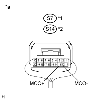
Text in Illustration *a Component with harness connected
(Roof Console Box Assembly (Telephone Microphone Assembly))
*1 except TMMK Made *2 for TMMK Made Connect an oscilloscope to terminals 13 (MCO+) and 12 (MCO-) of the S14 roof console box assembly (telephone microphone assembly) connector*2.
-
Check the waveform of the roof console box assembly (telephone microphone assembly) using the oscilloscope.
-
*1: except TMMK Made
-
*2: for TMMK Made
Result Result Proceed to A waveform synchronized with the voice input to the roof console box assembly (telephone microphone assembly) is output. A A waveform synchronized with the voice input to the roof console box assembly (telephone microphone assembly) is not output.
(for TMMK Made)
B A waveform synchronized with the voice input to the roof console box assembly (telephone microphone assembly) is not output.
(for TMC, TMMR Made)
C -
B
REPLACE ROOF CONSOLE BOX ASSEMBLY (TELEPHONE MICROPHONE ASSEMBLY) Click here
C
REPLACE ROOF CONSOLE BOX ASSEMBLY (TELEPHONE MICROPHONE ASSEMBLY) Click here
A
PROCEED TO NEXT SUSPECTED AREA SHOWN IN PROBLEM SYMPTOMS TABLE Click here
-