BRAKE MASTER CYLINDER (for LHD) INSTALLATION

-
INSPECT AND ADJUST BRAKE BOOSTER PUSH ROD (for TMMK Made)
Note
Make the adjustment with no vacuum in the brake booster assembly. (Depress the brake pedal several times with the engine stopped.)
Tech Tips
-
Adjustment of the brake booster push rod is required when the brake master cylinder sub-assembly is replaced with a new one.
-
Adjustment is not necessary when the removed brake master cylinder sub-assembly is reused and the brake booster assembly is replaced with a new one.
-
Apply chalk to the tip of the accessory tool.
Tech Tips
The accessory tool is enclosed with a new brake master cylinder sub-assembly.
-
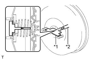
Text in Illustration *1 Accessory Tool *2 Brake Booster Push Rod Place the accessory tool on the brake booster assembly.
-
Measure the clearance between the brake booster push rod and accessory tool.
Standard clearance 0 mm (0 in.) Tech Tips
Adjust the clearance in the following cases:
-
If there is a clearance between the accessory tool and the shell of the brake booster (the accessory tool does not contact the body of the brake booster), the push rod is protruding too far.
-
If the chalk does not stick on the tip of the brake booster push rod, the push rod protrusion is insufficient.
-
-
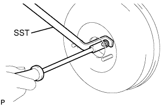
If the clearance is not as specified, adjust the push rod length by holding the rod using SST and turning the tip of the rod using a socket driver (7 mm).
- SST
- 09737-00020
Tech Tips
Check the push rod clearance again after adjustment.
-
-
INSTALL BRAKE MASTER CYLINDER O-RING
-
Install a new brake master cylinder O-ring to the brake master cylinder sub-assembly.
-
-
INSTALL BRAKE MASTER CYLINDER SUB-ASSEMBLY (for TMC, TMMR Made)
Note
When installing a new brake master cylinder sub-assembly, remove the protectors from the master cylinder piston and outlet ports.
-
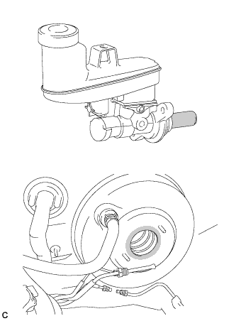
Apply a light layer of a grease enclosed with a new brake master cylinder sub-assembly or lithium soap base glycol grease to the circumference of the brake master cylinder sub-assembly and inner surface of the brake booster assembly as shown in the illustration.
Text in Illustration 
Apply Grease -
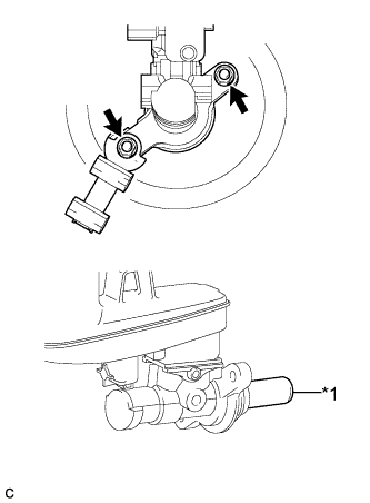
Text in Illustration *1 Master Cylinder Piston Install the brake master cylinder sub-assembly and front No. 1 brake tube way to the brake booster assembly with the 2 nuts.
- Torque:
- 13 N*m { 130 kgf*cm, 9 ft.*lbf }
Note
-
Do not hold the brake master cylinder sub-assembly by the master cylinder piston. Hold the brake master cylinder sub-assembly by its body or its reservoir when carrying it.
-
Do not pull out the master cylinder piston.
-
Do not strike or pinch the master cylinder piston, and do not cause any damage to the master cylinder piston by any other means.
-
When installing the brake master cylinder sub-assembly to the brake booster assembly, or when removing the brake master cylinder sub-assembly from the brake booster assembly, make sure that the brake master cylinder sub-assembly is kept horizontal or its tip faces downward (the master cylinder piston faces upward) to prevent the master cylinder piston from falling out.
-
Do not allow any foreign matter to contaminate the master cylinder piston. If any foreign matter gets on the master cylinder piston, remove it by using a piece of cloth and then apply an even layer of lithium soap base glycol grease around the circumference (sliding part) of the master cylinder piston.
-
Do not use any other types of grease.
-
Do not kink or damage the brake lines.
-
Do not allow brake lines to twist and interfere with other parts or vehicle body during flexible hose tightening.
-
Do not allow any foreign matter such as dirt or dust to enter the brake lines.
-
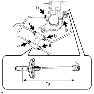
Text in Illustration *a Torque Wrench Fulcrum Length Using a union nut wrench, connect the 6 brake lines and install the brake master cylinder to way tube to the brake master cylinder sub-assembly.
- Torque:
- Specified tightening torque (a)
- 15 N*m { 155 kgf*cm, 11 ft.*lbf }
- Specified tightening torque (b)
- 20 N*m { 199 kgf*cm, 14 ft.*lbf }
Note
-
Do not kink or damage the brake lines.
-
Do not allow brake lines to twist and interfere with other parts or vehicle body during flexible hose tightening.
-
Do not allow any foreign matter such as dirt or dust to enter the brake lines.
Tech Tips
-
Calculate the torque wrench reading when changing the fulcrum length of the torque wrench Click here.
-
When using a union nut wrench (fulcrum length of 22 mm (0.866 in.)) + torque wrench (fulcrum length of 250 mm (9.84 in.)):
(a): 14 N*m (142 kgf*cm, 10 ft.*lbf)
-
When using a union nut wrench (fulcrum length of 20 mm (0.787 in.)) + torque wrench (fulcrum length of 250 mm (9.84 in.)):
(b): 18 N*m (184 kgf*cm, 13 ft.*lbf)
-
Connect the reservoir level switch connector and engage the clamp.
-
-
INSTALL BRAKE MASTER CYLINDER SUB-ASSEMBLY (for TMMK Made)
Note
When installing a new brake master cylinder sub-assembly, remove the protectors from the master cylinder piston and outlet ports.
-
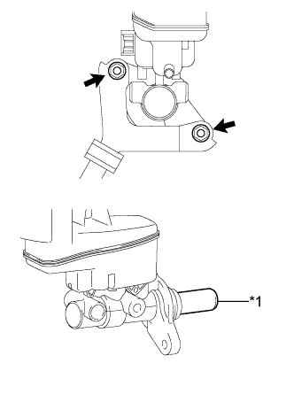
Text in Illustration *1 Master Cylinder Piston Install the brake master cylinder sub-assembly and front No. 1 brake tube way to the brake booster assembly with the 2 nuts.
- Torque:
- 13 N*m { 127 kgf*cm, 9 ft.*lbf }
Note
-
Do not hold the brake master cylinder sub-assembly by the master cylinder piston. Hold the brake master cylinder sub-assembly by its body or its reservoir when carrying it.
-
Do not pull out the master cylinder piston.
-
Do not strike or pinch the master cylinder piston, and do not cause any damage to the master cylinder piston by any other means.
-
When installing the brake master cylinder sub-assembly to the brake booster assembly, or when removing the brake master cylinder sub-assembly from the brake booster assembly, make sure that the brake master cylinder sub-assembly is kept horizontal or its tip faces downward (the master cylinder piston faces upward) to prevent the master cylinder piston from falling out.
-
Do not allow any foreign matter to contaminate the master cylinder piston. If any foreign matter gets on the master cylinder piston, remove it by using a piece of cloth and then apply an even layer of lithium soap base glycol grease around the circumference (sliding part) of the master cylinder piston.
-
Do not kink or damage the brake lines.
-
Do not allow brake lines to twist and interfere with other parts or vehicle body during flexible hose tightening.
-
Do not allow any foreign matter such as dirt or dust to enter the brake lines.
-
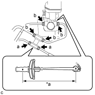
Text in Illustration *a Torque Wrench Fulcrum Length Using a union nut wrench, connect the 6 brake lines and install the brake master cylinder to way tube to the brake master cylinder sub-assembly.
- Torque:
- Specified tightening torque (a)
- 15 N*m { 155 kgf*cm, 11 ft.*lbf }
- Specified tightening torque (b)
- 20 N*m { 199 kgf*cm, 14 ft.*lbf }
Note
-
Do not kink or damage the brake lines.
-
Do not allow brake lines to twist and interfere with other parts or vehicle body during flexible hose tightening.
-
Do not allow any foreign matter such as dirt or dust to enter the brake lines.
Tech Tips
-
Calculate the torque wrench reading when changing the fulcrum length of the torque wrench Click here.
-
When using a union nut wrench (fulcrum length of 22 mm (0.866 in.)) + torque wrench (fulcrum length of 250 mm (9.84 in.)):
(a): 14 N*m (142 kgf*cm, 10 ft.*lbf)
-
When using a union nut wrench (fulcrum length of 20 mm (0.787 in.)) + torque wrench (fulcrum length of 250 mm (9.84 in.)):
(b): 18 N*m (184 kgf*cm, 13 ft.*lbf)
-
Connect the reservoir level switch connector and engage the clamp.
-
-
BLEED BRAKE SYSTEM
-
INSTALL AIR CLEANER CASE SUB-ASSEMBLY (for 6AR-FSE)
-
INSTALL AIR CLEANER FILTER ELEMENT SUB-ASSEMBLY (for 6AR-FSE)
-
INSTALL AIR CLEANER CAP WITH AIR CLEANER HOSE (for 6AR-FSE)
-
Connect the air cleaner cap with air cleaner hose to the throttle body with motor assembly.
-
Install the air cleaner cap with air cleaner hose with the 2 guides and 2 air cleaner cap clamps.
-
Tighten the hose clamp.
-
Connect the union to connector tube hose to the air cleaner hose sub-assembly.
-
Engage the wire harness clamp.
-
Connect the mass air flow meter sub-assembly connector.
-
Engage the ventilation hose clamp.
-
Connect the ventilation hose to the cylinder head cover sub-assembly and slide the clip to secure it.
-
-
INSTALL INLET AIR CLEANER ASSEMBLY (for 6AR-FSE)
-
INSTALL NO. 1 ENGINE COVER SUB-ASSEMBLY (for 6AR-FSE)
-
INSTALL AIR CLEANER CASE SUB-ASSEMBLY (for 2AR-FE)
-
INSTALL AIR CLEANER FILTER ELEMENT SUB-ASSEMBLY (for 2AR-FE)
-
INSTALL AIR CLEANER CAP SUB-ASSEMBLY (for 2AR-FE)
-
Install the air cleaner cap sub-assembly with the 2 clamps.
-
Install the air cleaner hose with the hose clamp.
-
Connect the ventilation hose to the cylinder head cover.
-
Install the fuel vapor feed hose to the air cleaner hose.
-
Connect the mass air flow meter connector and 2 wire harness clamps to the air cleaner cap sub-assembly.
-
Connect the vacuum switching valve assembly to the air cleaner hose.
-
-
INSTALL INLET AIR CLEANER ASSEMBLY (for 2AR-FE)
-
INSTALL AIR CLEANER CASE SUB-ASSEMBLY (for 2GR-FE)
-
INSTALL AIR CLEANER FILTER ELEMENT SUB-ASSEMBLY (for 2GR-FE)
-
INSTALL AIR CLEANER CAP SUB-ASSEMBLY (for 2GR-FE)
-
Connect the air cleaner cap sub-assembly to the throttle with motor body assembly with the hose clamp.
-
Install the air cleaner cap with hose to the air cleaner case with the 2 clamps.
-
Connect the wire harness clamp and mass air flow meter connector.
-
Connect the 3 hoses.
-
Connect the ventilation hose.
-
Connect the mass air flow meter connector and wire harness clamp.
-
-
INSTALL INLET NO. 2 AIR CLEANER (for 2GR-FE)
-
INSTALL COOL AIR INTAKE DUCT SEAL (for TMC, TMMR Made)
-
INSTALL COOL AIR INTAKE DUCT SEAL (for TMMK Made)
-
Install the cool air intake duct seal with the 9 clips.
-
-
INSTALL FRONT OUTER COWL TOP PANEL SUB-ASSEMBLY
-
Install the front outer cowl top panel sub-assembly with the 10 bolts.
- Torque:
- 10 N*m { 102 kgf*cm, 7 ft.*lbf }
-
Engage the 2 clamps to install the wire harness to the front outer cowl top panel sub-assembly.
-
w/ Windshield Deicer System:
-
Connect the connector.
-
Engage the 2 clamps to install the wire harness to the front outer cowl top panel sub-assembly.
-
-
w/ Heated Windshield Defroster System:
-
Connect the 2 connectors.
-
Engage the 4 clamps to install the wire harness to the front outer cowl top panel sub-assembly.
-
-
-
INSTALL WINDSHIELD WIPER MOTOR AND LINK ASSEMBLY