BRAKE BOOSTER (for RHD) INSTALLATION

-
INSTALL CHECK VALVE GROMMET
-
Install a new check valve grommet to the brake booster assembly.
-
-
INSTALL BRAKE VACUUM CHECK VALVE ASSEMBLY
-
Install the brake vacuum check valve assembly to the brake booster assembly.
-
-
INSTALL BRAKE MASTER CYLINDER PUSH ROD CLEVIS
-
Temporarily install the lock nut and brake master cylinder push rod clevis to the brake booster assembly.
-
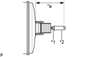
Text in Illustration *1 Lock Nut *2 Brake Master Cylinder Push Rod Clevis *a Push Rod Length Set the push rod length as shown in the illustration.
Push rod length 148.6 to 149.6 mm (5.86 to 5.88 in.) -
Tighten the lock nut.
- Torque:
- 26 N*m { 265 kgf*cm, 19 ft.*lbf }
-
-
INSTALL BRAKE BOOSTER GASKET
-
Install a new brake booster gasket to the brake booster assembly.
-
-
INSTALL BRAKE BOOSTER ASSEMBLY
-
Install the brake booster assembly to the vehicle body with the 4 nuts.
- Torque:
- 13 N*m { 131 kgf*cm, 9 ft.*lbf }
Note
Do not kink or damage the brake lines, air conditioning tube and accessory assembly or suction pipe sub-assembly.
-
-
INSTALL PUSH ROD PIN
-
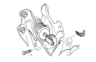
Apply lithium soap base glycol grease to the push rod pin.
Text in Illustration 
Lithium Soap Base Glycol Grease -
Connect the brake master cylinder push rod clevis to the brake pedal support assembly with the push rod pin, and install a new clip as shown in the illustration.
Note
-
Be sure to insert the pin with its clip end facing the outside of the vehicle.
-
Make sure that the brake master cylinder push rod clevis moves sideway.
-
-
-
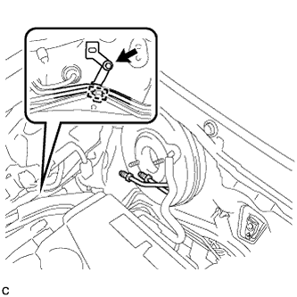
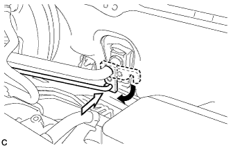
CONNECT UNION TO CHECK VALVE HOSE
-
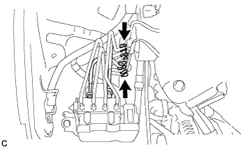
Connect the union to check valve hose to the brake booster assembly, and slide the clip to secure it.
-
-
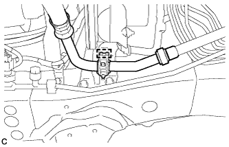
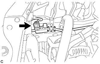
INSTALL VACUUM SWITCHING VALVE ASSEMBLY
-
Install the vacuum switching valve assembly with the bolt.
- Torque:
- 9.0 N*m { 92 kgf*cm, 80 in.*lbf }
-
Connect the 2 vacuum hoses and connector.
-
Connect the union to check valve hose and wire harness clamp.
-
-
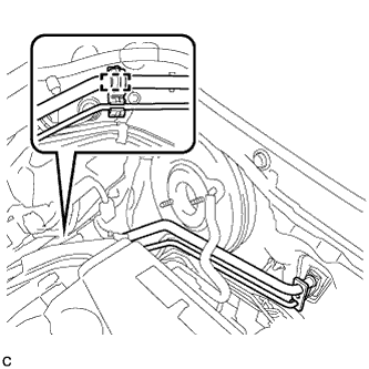
CONNECT BRAKE LINE
-
Install 2 new clamps to the brake lines.
-
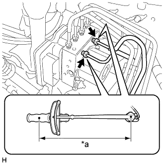
Text in Illustration *a Torque Wrench Fulcrum Length Using a union nut wrench, connect the 2 brake lines to the brake actuator assembly.
- Torque:
- Specified tightening torque
- 20 N*m { 199 kgf*cm, 14 ft.*lbf }
Note
-
Do not kink or damage the brake lines.
-
Do not allow brake lines to twist and interfere with other parts or vehicle body during flexible hose tightening.
-
Do not allow any foreign matter such as dirt or dust to enter the brake lines.
Tech Tips
-
Calculate the torque wrench reading when changing the fulcrum length of the torque wrench Click here.
-
When using a union nut wrench (fulcrum length of 20 mm (0.787 in.)) + torque wrench (fulcrum length of 250 mm (9.84 in.)):
18 N*m (184 kgf*cm, 13 ft.*lbf)
-
-
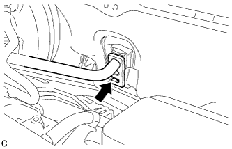
INSTALL NO. 1 BRAKE TUBE CLAMP
-
Install a new No. 1 brake tube clamp to the vehicle body.
- Torque:
- 7.8 N*m { 80 kgf*cm, 69 in.*lbf }
-
Engage the brake lines to the clamp.
Note
Do not kink or damage the brake lines.
-
-
INSTALL SUCTION PIPE SUB-ASSEMBLY
-
Remove the attached vinyl tape from the openings of the disconnected parts.
-
Sufficiently apply compressor oil to a new O-ring, fitting surface of the suction pipe sub-assembly and air conditioning unit.
Compressor oil ND-OIL 8 or equivalent -
Install the O-ring on the suction pipe sub-assembly.
Note
Keep the O-ring and O-ring fitting surfaces free from dirt or any foreign matter.
-
Insert the suction pipe sub-assembly to the air conditioning unit.
Note
-
Insert the pipe joint into the fitting hole securely.
-
Do not deform the piping.
-
Do not damage the plastic clamp.
-
-
Install the clamp with suction pipe sub-assembly and air conditioning tube and accessory assembly to the No. 1 brake tube clamp.
Note
-
Do not deform the air conditioning tube and accessory assembly or suction pipe sub-assembly.
-
Do not damage the plastic clamp.
-
-
Install the clamp to the brake actuator bracket assembly.
Note
-
Do not deform the suction pipe sub-assembly.
-
Do not damage the plastic clamp.
-
-
-
INSTALL AIR CONDITIONING TUBE AND ACCESSORY ASSEMBLY
-
Remove the attached vinyl tape from the openings of the disconnected parts.
-
Sufficiently apply compressor oil to 2 new O-rings, the fitting surface of the air conditioning tube and accessory assembly, cooler condenser assembly and air conditioning unit.
Compressor oil ND-OIL 8 or equivalent -
Install the 2 O-rings on the air conditioning tube and accessory assembly.
Note
Keep the O-ring and O-ring fitting surfaces free from dirt or any foreign matter.
-
Insert the air conditioning tube and accessory assembly to the cooler condenser assembly.
-
Install the bolt.
- Torque:
- 9.8 N*m { 100 kgf*cm, 87 in.*lbf }
-
Insert the air conditioning tube and accessory assembly to the air conditioning unit.
Note
Insert the pipe joint into the fitting hole securely.
-
Turn the hook connector and install the bolt.
- Torque:
- 9.8 N*m { 100 kgf*cm, 87 in.*lbf }
-
Install the clamp to the vehicle body and connect the pressure sensor connector.
Note
-
Do not deform the piping.
-
Do not damage the plastic clamp.
-
-
-
INSTALL RADIATOR SIDE DEFLECTOR RH
-
INSTALL BRAKE MASTER CYLINDER SUB-ASSEMBLY
-
CONNECT CABLE TO NEGATIVE BATTERY TERMINAL
Note
When disconnecting the cable, some systems need to be initialized after the cable is reconnected Click here.
-
CHARGE AIR CONDITIONING SYSTEM WITH REFRIGERANT
-
WARM UP ENGINE
-
INSPECT FOR REFRIGERANT LEAK
-
INSTALL FRONT BUMPER COVER
-
INSPECT AND ADJUST BRAKE PEDAL