HAZARD WARNING SWITCH (for TMC, TMMR Made) REMOVAL
-
PRECAUTION (w/ Navigation System)
Note
After turning the Ignition switch off, waiting time may be required before disconnecting the cable from the negative (-) battery terminal. Therefore, make sure to read the disconnecting the cable from the negative (-) battery terminal notices before proceeding with work Click here.
-
DISCONNECT CABLE FROM NEGATIVE BATTERY TERMINAL (w/ Navigation System)
Note
When disconnecting the cable, some systems need to be initialized after the cable is reconnected Click here.
-
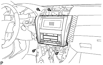
REMOVE FRONT PANEL GARNISH LH
-
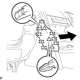
Disengage the 3 clips and 8 guides to remove the front panel garnish LH as shown in the illustration.
-
-
REMOVE FRONT PANEL GARNISH RH
-
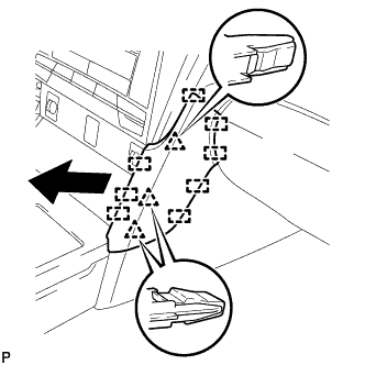
Disengage the 3 clips and 8 guides to remove the front panel garnish RH.
-
-
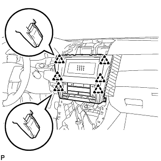
REMOVE CENTER INSTRUMENT CLUSTER FINISH PANEL SUB-ASSEMBLY
-
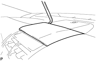
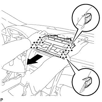
Using a moulding remover, pry up on the center instrument cluster finish panel sub-assembly until there is enough of a gap to make it possible to pull on the panel by hand.
-
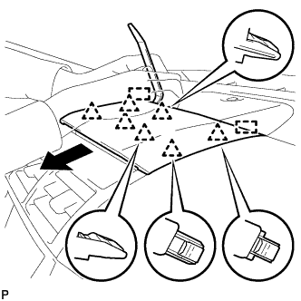
Pull the center instrument cluster finish panel sub-assembly in the direction indicated by the arrow to disengage the 7 clips and 2 guides to remove the center instrument cluster finish panel sub-assembly as shown in the illustration.
-
-
REMOVE NO. 2 INSTRUMENT PANEL REGISTER ASSEMBLY
-
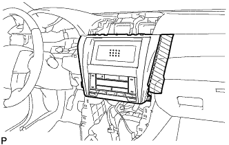
Pull the No. 2 instrument panel register assembly in the direction indicated by the arrow to disengage the 4 clips as shown in the illustration.
-
Disconnect the connector to remove the No. 2 instrument panel register assembly.
-
-
REMOVE FRONT CONSOLE UPPER PANEL GARNISH
-
for Blank Type:
-
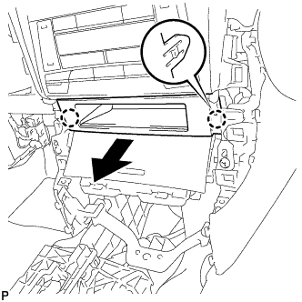
Disengage the 2 claws and remove the front console upper panel garnish as shown in the illustration.
-
-
for 3 Switch Hole Type:
-
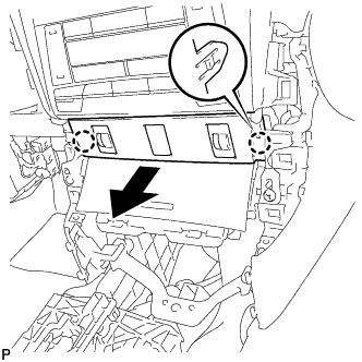
Disengage the 2 claws as shown in the illustration.
-
Disconnect each connector to remove the front console upper panel garnish.
-
-
-
REMOVE CENTER INSTRUMENT CLUSTER FINISH PANEL WITH AIR CONDITIONING CONTROL ASSEMBLY (w/o Radio Receiver)
-
Apply protective tape to the area shown in the illustration.
Text in Illustration 
Protective Tape -
Remove the 4 bolts <C>.
-
Disengage the 6 clips.
-
Disconnect the connector to remove the center instrument cluster finish panel with air conditioning control assembly.
-
-
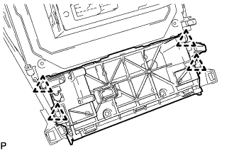
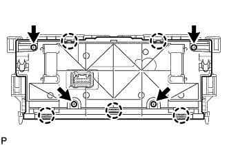
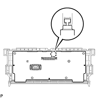
REMOVE RADIO RECEIVER ASSEMBLY WITH AIR CONDITIONING CONTROL ASSEMBLY (for Radio Receiver Type)
-
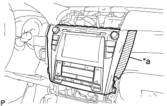
Text in Illustration *a Protective Tape Apply protective tape to the area shown in the illustration.
-
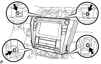
Remove the 4 bolts.
-
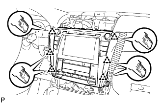
Pull the radio receiver assembly with air conditioning control assembly toward the rear of the vehicle and disengage the 6 clips.
-
Disconnect each connector and remove the radio receiver assembly with air conditioning control assembly.
-
-
REMOVE NAVIGATION RECEIVER ASSEMBLY WITH AIR CONDITIONING CONTROL ASSEMBLY (for Navigation Receiver Type)
-
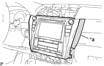
Text in Illustration *a Protective Tape Apply protective tape to the area shown in the illustration.
-
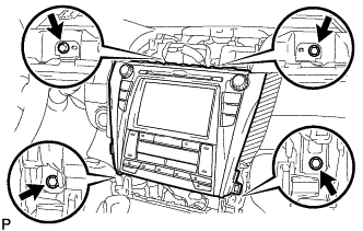
Remove the 4 bolts.
-
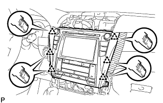
Pull the navigation receiver assembly with air conditioning control assembly toward the rear of the vehicle and disengage the 6 clips.
-
Disconnect each connector and remove the navigation receiver assembly with air conditioning control assembly.
-
-
REMOVE NO. 1 RADIO BRACKET (w/o Radio Receiver)
-
Remove the 3 screws.
-
Disengage the claw to remove the No. 1 radio bracket.
-
-
REMOVE NO. 2 RADIO BRACKET (w/o Radio Receiver)
-
Remove the 3 screws.
-
Disengage the claw to remove the No. 2 radio bracket and radio tuner opening cover.
-
-
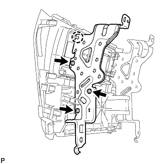
REMOVE NO. 1 RADIO BRACKET (for Radio Receiver Type)
-
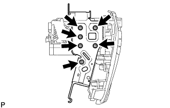
w/o Navigation System:
-
Remove the 4 screws and No. 1 radio bracket.
-
-
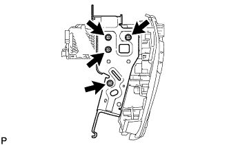
w/ Navigation System:
-
Remove the 6 screws and No. 1 radio bracket.
-
-
-
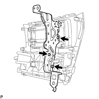
REMOVE NO. 2 RADIO BRACKET (for Radio Receiver Type)
-
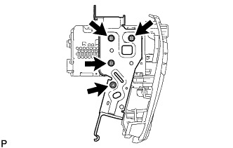
w/o Navigation System:
-
Remove the 4 screws and No. 2 radio bracket.
-
-
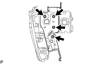
w/ Navigation System:
-
Remove the 6 screws and No. 2 radio bracket.
-
-
-
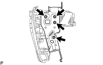
REMOVE NO. 1 RADIO BRACKET (for Navigation Receiver Type)
-
Remove the 4 screws and No. 1 radio bracket.
-
-
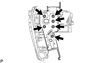
REMOVE NO. 2 RADIO BRACKET (for Navigation Receiver Type)
-
Remove the 4 screws and No. 2 radio bracket.
-
-
REMOVE AIR CONDITIONING CONTROL ASSEMBLY (HAZARD SWITCH)
-
Disengage the 4 clips and remove the air conditioning control assembly.
-
-
REMOVE HEATER CONTROL SWITCH BOARD
Note
When disassembling the air conditioning control assembly, eliminate static electricity by touching the vehicle body to prevent the components from being damaged.
-
Remove the 4 screws.
-
Disengage the 5 claws and remove the heater control retainer RH from the heater control housing sub-assembly.
-
Disengage the claw to remove the heater control switch board from the heater control housing sub-assembly.
Note
Make sure that the hazard switch is off before removing the heater control switch board to prevent the heater control switch board and heater control housing sub-assembly from being damaged.
-