FUEL INJECTOR (for Port Injection) INSTALLATION
-
INSTALL PORT FUEL INJECTOR ASSEMBLY
Tech Tips
Perform "Inspection After Repair" after replacing a port fuel injector assembly Click here.
-
Apply a light coat of spindle oil or gasoline to a new O-ring, and install one to each port fuel injector assembly.
Note
Check that there is no damage or foreign matter on the groove of the port fuel injector assembly when installing each O-ring to the port fuel injector assembly.
-
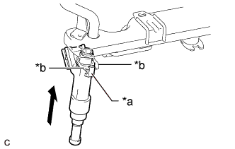
Text in Illustration *a Claw *b Stopper Install the 4 port fuel injector assemblies to the fuel delivery pipe.
Note
-
Make sure that the port fuel injector assembly is located within the stopper as shown in the illustration.
-
Check that there is no damage or foreign matter on the port fuel injector assembly installation holes.
-
When installing the O-rings, make sure they do not become pinched or cut.
-
-
-
INSTALL INJECTOR VIBRATION INSULATOR
-
Install 4 new injector vibration insulators to the cylinder head sub-assembly.
-
-
INSTALL FUEL DELIVERY SPACER
-
Install the 2 fuel delivery spacers to the cylinder head sub-assembly.
-
-
INSTALL FUEL DELIVERY PIPE
-
Place the fuel delivery pipe with the port fuel injector assemblies onto the cylinder head sub-assembly.
Note
Be careful not to drop the port fuel injector assemblies when installing the fuel delivery pipe.
-
Install the fuel delivery pipe with the port fuel injector assemblies with the 2 bolts.
- Torque:
- 21 N*m { 214 kgf*cm, 15 ft.*lbf }
-
-
CONNECT NO. 8 ENGINE WIRE
-
Engage the 3 clamps to connect the No. 8 engine wire to the fuel delivery pipe.
-
Connect the 4 port fuel injector assembly connectors.
-
-
CONNECT NO. 2 VENTILATION HOSE
-
Connect the No. 2 ventilation hose to the PCV valve (ventilation valve sub-assembly) and slide the clip to secure it.
-
-
CONNECT FUEL TUBE SUB-ASSEMBLY
Note
Check that there is no damage or foreign matter on the connecting parts of the fuel lines.
-
Connect the fuel tube sub-assembly to the fuel delivery pipe.
-
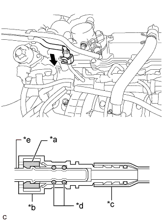
Text in Illustration *a Retainer *b Fuel Tube Connector *c Nylon Tube *d O-ring *e Fuel Pipe 
Push Align the fuel tube connector with the fuel pipe, and push them together until the fuel tube connector makes a "click" sound. If it is difficult to push the fuel pipe into the fuel tube connector, apply a small amount of clean engine oil to the tip of the fuel pipe and reinsert it.
-
After connecting the fuel pipes, check that the fuel pipe and fuel tube connector are securely connected by pulling on them.
-
Push in the fuel tube connector cover.
-
-
-
TEMPORARILY INSTALL NO. 1 FUEL PIPE SUB-ASSEMBLY
-
Connect the No. 1 fuel pipe sub-assembly to the fuel delivery pipe sub-assembly and tighten the union nut by hand.
-
Connect the No. 1 fuel pipe sub-assembly to the fuel pump with seal sub-assembly and tighten the union nut by hand.
Note
Do not damage the seals of the union nuts of the No. 1 fuel pipe sub-assembly when installing.
-
-
INSTALL NO. 1 FUEL PIPE SUB-ASSEMBLY
-
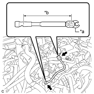
Text in Illustration *a 17 mm Union Nut Wrench *b Torque Wrench Fulcrum Length Using a 17 mm union nut wrench, tighten the union nuts on the fuel pump with seal sub-assembly side of the No. 1 fuel pipe sub-assembly.
- Torque:
- 35 N*m { 357 kgf*cm, 26 ft.*lbf }
Tech Tips
-
Calculate the torque wrench reading when changing the fulcrum length of the torque wrench Click here.
-
When using a 17 mm union nut wrench (fulcrum length of 30 mm (1.18 in.)) + torque wrench (fulcrum length of 180 mm (7.09 in.)): 30 N*m (306 kgf*cm, 22 ft.*lbf)
-
Using a 17 mm union nut wrench, tighten the union nuts on the fuel delivery pipe sub-assembly side of the No. 1 fuel pipe sub-assembly.
- Torque:
- 35 N*m { 357 kgf*cm, 26 ft.*lbf }
Tech Tips
-
Calculate the torque wrench reading when changing the fulcrum length of the torque wrench Click here.
-
When using a 17 mm union nut wrench (fulcrum length of 30 mm (1.18 in.)) + torque wrench (fulcrum length of 180 mm (7.09 in.)): 30 N*m (306 kgf*cm, 22 ft.*lbf)
-
-
INSTALL THROTTLE BODY WITH MOTOR ASSEMBLY
-
INSTALL FUEL PUMP PROTECTOR
-
Install the fuel pump protector to the cylinder head cover sub-assembly with the 2 bolts.
- Torque:
- 21 N*m { 214 kgf*cm, 15 ft.*lbf }
-
-
CONNECT CABLE TO NEGATIVE BATTERY TERMINAL
Note
When disconnecting the cable, some systems need to be initialized after the cable is reconnected Click here.
-
INSPECT FOR FUEL LEAK
-
Check fuel pump operation.
-
Connect the GTS to the DLC3.
-
Turn the engine switch to on (IG).
Note
Do not start the engine.
-
Turn the GTS on.
-
Enter the following menus: Powertrain / Engine / Active Test / Activate the Circuit Relay.
-
Check for pressure in the fuel tube sub-assembly from the fuel line. Check that sounds of fuel flowing from the fuel tank assembly can be heard. If no sounds can be heard, check the integration relay, fuel pump, ECM and wiring connectors.
-
-
Inspect for fuel leaks.
-
Check that there are no fuel leaks from the fuel system after doing any maintenance or repairs. If there is a fuel leak, repair or replace parts as necessary.
-
-
Turn the engine switch off.
-
Disconnect the GTS from the DLC3.
-
-
PERFORM INITIALIZATION
-
Perform "Inspection After Repair" after replacing a port fuel injector assembly Click here.
-