ENGINE ASSEMBLY INSTALLATION

Tech Tips
Perform "Inspection After Repair" after replacing the engine assembly Click here.
-
REMOVE ENGINE STAND
-
INSTALL DRIVE PLATE AND RING GEAR SUB-ASSEMBLY
-
Using SST, hold the crankshaft pulley.
- SST
- 09213-70011 ( 09213-70020 )
- 09330-00021
-
Clean the 8 bolts and 8 bolt holes.
-
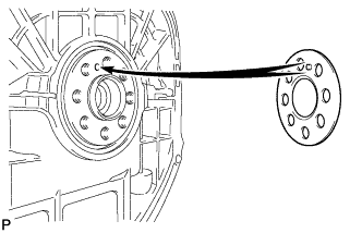
Install the front drive plate spacer.
Tech Tips
Align the pin of the front drive plate spacer with the pin hole of the crankshaft.
-
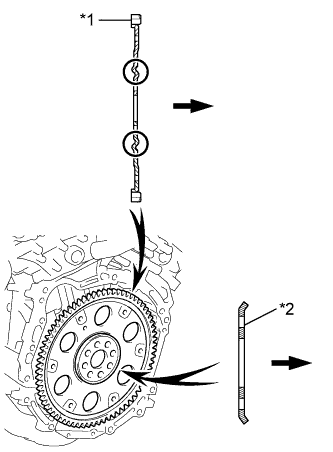
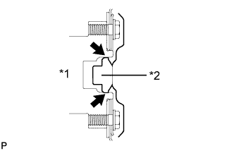
Text in Illustration *1 Drive Plate *2 Rear Spacer 
Transaxle Side Install the drive plate and ring gear sub-assembly and rear drive plate spacer onto the crankshaft.
-
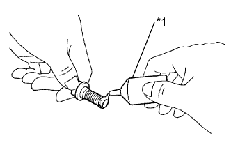
Text in Illustration *1 Adhesive Apply adhesive to 2 or 3 threads of each bolt.
Adhesive Toyota Genuine Adhesive 1324, Three Bond 1324 or equivalent -
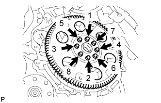
In several steps, uniformly install and tighten the 8 bolts in the sequence shown in the illustration.
- Torque:
- 83 N*m { 846 kgf*cm, 61 ft.*lbf }
Note
Do not start the engine for at least an hour after installing the drive plate.
-
-
INSTALL DRIVE SHAFT BEARING BRACKET
-
Install the drive shaft bearing bracket with the 3 bolts.
- Torque:
- 64 N*m { 650 kgf*cm, 47 ft.*lbf }
-
-
INSTALL ENGINE MOUNTING BRACKET RH
-
Install the engine mounting bracket RH with the 3 bolts.
- Torque:
- 54 N*m { 551 kgf*cm, 40 ft.*lbf }
-
-
INSTALL AUTOMATIC TRANSAXLE ASSEMBLY
-
Text in Illustration *1 Crankshaft *2 Torque Converter Centerpiece Apply clutch spline grease to the surface of the crankshaft that contacts the torque converter centerpiece.
Clutch spline grease Toyota Genuine Clutch Spline Grease or equivalent Maximum grease amount Approximately 1 g (0.0353 oz.) -
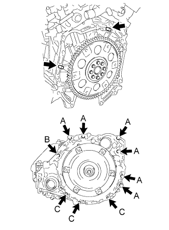
While keeping the engine and automatic transaxle assembly horizontal, align the knock pins with the holes in the automatic transaxle assembly and install the 10 bolts shown in the illustration.
- Torque:
- Bolt A
- 64 N*m { 653 kgf*cm, 47 ft.*lbf }
- Bolt B
- 64 N*m { 653 kgf*cm, 47 ft.*lbf }
- Bolt C
- 43 N*m { 438 kgf*cm, 32 ft.*lbf }
Note
-
Confirm that the 2 knock pins are installed to the transaxle contact surface of the engine cylinder block before installing the transaxle.
-
Do not forcibly pry on the automatic transaxle assembly.
-
Check that the torque converter rotates.
Tech Tips
Bolt length:
-
Bolt A: 55 mm (2.17 in.)
-
Bolt B: 50 mm (1.97 in.)
-
Bolt C: 33 mm (1.30 in.)
-
Clean and degrease the bolt and the installation hole in the automatic transaxle.
-
Apply a few drops of adhesive to 2 or 3 threads at the tip of each of the bolt.
Adhesive Toyota Genuine Adhesive 1344, Three Bond 1344 or equivalent -
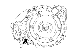
Install the bolt.
- Torque:
- Bolt D
- 46 N*m { 469 kgf*cm, 34 ft.*lbf }
Tech Tips
Bolt length:
-
Bolt D: 41 mm (1.61 in.)
-
-
INSTALL ENGINE WIRE
-
Install the engine wire to the engine with transaxle.
-
-
INSTALL FRONT ENGINE MOUNTING INSULATOR ASSEMBLY
-
Temporarily install the front engine mounting insulator assembly with the 3 bolts.
Tech Tips
Perform this procedure only when replacement of the front engine mounting insulator assembly is necessary.
-
-
INSTALL ENGINE MOUNTING INSULATOR LH
-
Temporarily install the engine mounting insulator LH with the 3 bolts.
Tech Tips
Perform this procedure only when replacement of the engine mounting insulator LH is necessary.
-
-
INSTALL ENGINE MOUNTING INSULATOR RH
-
Temporarily install the engine mounting insulator RH with the 3 bolts.
Tech Tips
Perform this procedure only when replacement of the engine mounting insulator RH is necessary.
-
-
INSTALL FRONT FRAME ASSEMBLY
-
Install the engine mounting insulator RH with the nut.
- Torque:
- 95 N*m { 969 kgf*cm, 70 ft.*lbf }
-
Install the engine mounting insulator LH with the nut.
- Torque:
- 95 N*m { 969 kgf*cm, 70 ft.*lbf }
-
Install the front engine mounting insulator assembly with the bolt.
- Torque:
- 87 N*m { 888 kgf*cm, 65 ft.*lbf }
-
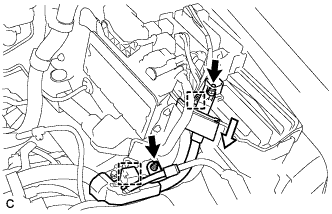
Connect the 2 wire clamps and vacuum switching valve connector.
-
Connect the 2 wire clamps and oil pressure switch connector.
-
Fully tighten the 9 temporarily installed nuts of the engine mounting insulators to the specified torque.
Tech Tips
Perform this procedure only when replacement of the engine mounting insulator is necessary.
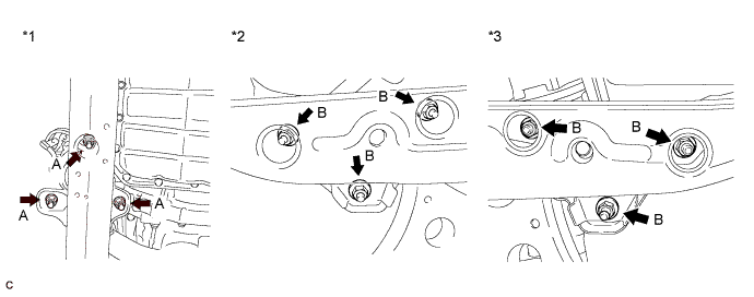
Text in Illustration *1 Front Engine Mounting Insulator Assembly *2 Engine Mounting Insulator RH *3 Engine Mounting Insulator LH - - - Torque:
- A
- 52 N*m { 530 kgf*cm, 38 ft.*lbf }
- Torque:
- B
- 87 N*m { 887 kgf*cm, 64 ft.*lbf }
-
Install the 4 hole plugs.
Tech Tips
Perform this procedure only when replacement of the engine mounting insulator is necessary.
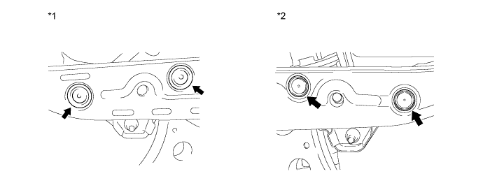
Text in Illustration *1 Engine Mounting Insulator RH *2 Engine Mounting Insulator LH
-
-
INSTALL COMPRESSOR AND MAGNETIC CLUTCH
-
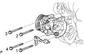
Install the compressor and magnetic clutch and bracket with the 4 bolts.
- Torque:
- 25 N*m { 250 kgf*cm, 18 ft.*lbf }
Tech Tips
Tighten the bolts in the order shown in the illustration.
-
-
INSTALL GENERATOR ASSEMBLY
-
Install the generator assembly with the 2 bolts.
- Torque:
- 43 N*m { 438 kgf*cm, 32 ft.*lbf }
-
Connect the wire harness clamp.
-
Install the generator bracket with the 2 bolts.
- Torque:
- 20 N*m { 204 kgf*cm, 15 ft.*lbf }
-
Connect the generator connector to the generator assembly.
-
Install the generator wire with the bolt.
- Torque:
- 8.4 N*m { 86 kgf*cm, 74 in.*lbf }
-
Install the nut and connect the wire harness to terminal B.
- Torque:
- 9.8 N*m { 100 kgf*cm, 87 in.*lbf }
-
Install the terminal cap.
-
-
INSTALL V-RIBBED BELT
-
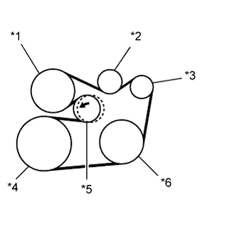
Text in Illustration *1 Water Pump *2 Idler *3 Generator *4 Crankshaft *5 Tensioner *6 A/C Compressor Install the V-ribbed belt.
-
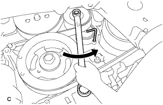
Turn the V-ribbed belt tensioner counterclockwise and remove the 5 mm hexagon wrench.
-
After installing the V-ribbed belt, check that it fits properly in the ribbed grooves. Confirm that the belt has not slipped out of the grooves on the bottom of the crank pulley by hand.
-
-
INSTALL ENGINE ASSEMBLY WITH TRANSAXLE
-
Set the engine assembly with transaxle on an engine lifter.
Note
-
Install a height adjustment attachment and plate lift attachment onto the engine assembly with transaxle.
-
Do not position a height adjustment attachment or plate lift attachment onto the front frame assembly.
-
Servicing an engine assembly while it is hanging is dangerous. This can be done only when installing/removing the engine assembly to/from an engine stand.
-
To prevent the oil pan from deforming, do not place any attachments onto the oil pan of the engine assembly with transaxle.
-
Make sure to support the engine assembly with transaxle securely to prevent it from falling.
-
-
Remove the engine hangers Click here.
-
Install the engine assembly with transaxle to the vehicle.
Note
-
Do not raise the engine more than necessary. If the engine is raised excessively, the vehicle may also be lifted up.
-
Make sure that the engine is clear of all wiring and hoses.
-
While raising the engine into the vehicle, do not allow it to contact the vehicle.
-
-
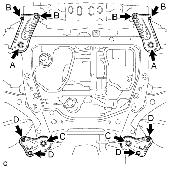
Install the frame side rail plates RH and LH with the 4 bolts and 2 nuts.
- Torque:
- A
- 85 N*m { 867 kgf*cm, 62 ft.*lbf }
- B
- 32 N*m { 329 kgf*cm, 24 ft.*lbf }
-
Install the front suspension member rear braces RH and LH with the 4 bolts and 2 nuts.
- Torque:
- C
- 85 N*m { 867 kgf*cm, 62 ft.*lbf }
- D
- 32 N*m { 329 kgf*cm, 24 ft.*lbf }
Tech Tips
Perform "Inspection After Repair" after replacing the engine assembly Click here.
-
-
INSTALL DRIVE PLATE AND TORQUE CONVERTER SETTING BOLT
-
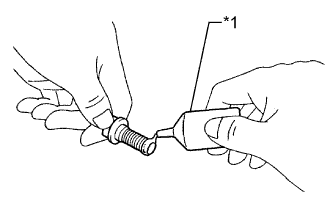
Text in Illustration *1 Adhesive 1324 Apply a few drops of adhesive to 2 or 3 threads at the tip of each of the 6 torque converter setting bolts.
Adhesive Toyota Genuine Adhesive 1324, Three Bond 1324 or equivalent. -
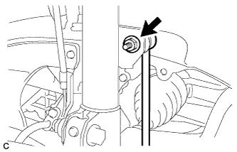
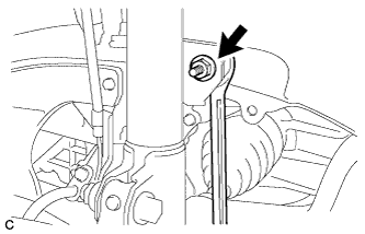
Turn the crankshaft to gain access to the installation locations of the 6 torque converter setting bolts and install each bolt while holding the crankshaft pulley bolt with a wrench.
- Torque:
- 41 N*m { 418 kgf*cm, 30 ft.*lbf }
Note
First install the black colored bolt, and then the remaining 5 silver colored bolts.
-
-
INSTALL NO. 1 EXHAUST PIPE SUPPORT BRACKET SUB-ASSEMBLY
-
Install the No. 1 exhaust pipe support bracket sub-assembly with the 2 bolts.
- Torque:
- 7.8 N*m { 80 kgf*cm, 69 in.*lbf }
-
-
INSTALL NO. 1 EXHAUST PIPE SUPPORT BRACKET
-
Install the No. 1 exhaust pipe support bracket with the bolt.
- Torque:
- 21 N*m { 214 kgf*cm, 15 ft.*lbf }
-
-
INSTALL FRONT DRIVE SHAFT HOLE SNAP RING LH
-
Install a new front drive shaft hole snap ring LH.
Note
Face the end gap of the front drive shaft hole snap ring downward.
-
-
INSTALL FRONT DRIVE SHAFT ASSEMBLY LH
-
Coat the spline of the front drive inboard joint assembly with ATF WS.
-
Coat the lip of the transaxle case oil seal with MP grease.
-
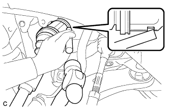
Align the inboard joint splines, and using a brass bar and a hammer, install the front drive shaft assembly LH.
Note
-
Face the end gap of the front drive shaft hole snap ring LH downward.
-
Do not damage the transaxle case oil seal.
-
Do not damage the front axle inboard joint boot.
-
Make sure to center the front drive shaft assembly LH during installation to prevent damage to the front drive shaft hole snap ring LH.
Tech Tips
Confirm whether the drive shaft is securely driven in by checking the reaction force and sound.
-
-
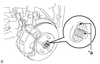
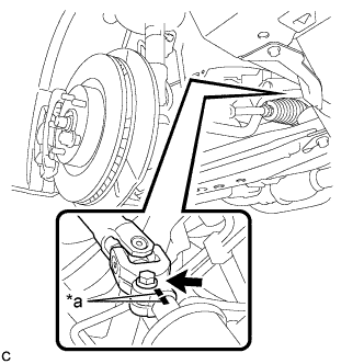
Text in Illustration *a Matchmark Align the matchmarks and install the front drive shaft assembly LH to the front axle hub sub-assembly.
Note
Be careful not to damage the front axle outboard joint boot or speed sensor rotor.
-
-
INSTALL FRONT DRIVE SHAFT ASSEMBLY RH
-
Coat the spline of the front drive inboard joint assembly with ATF WS.
-
Coat the lip of the front transaxle case oil seal with MP grease.
-
Install a new bearing bracket hole snap ring to the front drive shaft assembly RH.
-
Install the front drive shaft assembly RH.
Note
-
Do not damage the front transaxle case oil seal.
-
Do not damage the front axle inboard joint boot.
-
When inserting the front drive shaft assembly RH, keep it level.
-
-
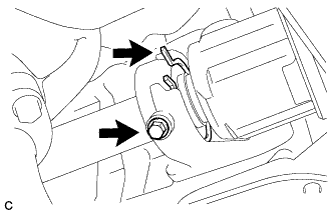
Install the bearing bracket hole snap ring and a new bolt.
- Torque:
- 32 N*m { 330 kgf*cm, 24 ft.*lbf }
-
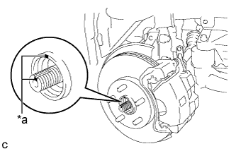
Text in Illustration *a Matchmark Align the matchmarks and install the front drive shaft assembly RH to the front axle hub sub-assembly.
Note
Be careful not to damage the front axle outboard joint boot or speed sensor rotor.
-
-
CONNECT FRONT LOWER NO. 1 SUSPENSION ARM SUB-ASSEMBLY LH
-
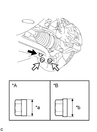
Text in Illustration *A for TMC, TMMR Made *B for TMMK Made *a 20 mm (0.787 in.) *b 22 mm (0.866 in.) Bolt 
Nut Connect the front lower No. 1 suspension arm sub-assembly to the front lower ball joint assembly with the bolt and 2 nuts.
- Torque:
- for TMC, TMMR Made
- 75 N*m { 765 kgf*cm, 55 ft.*lbf }
- for TMMK Made
- 92 N*m { 938 kgf*cm, 68 ft.*lbf }
Note
-
The tightening torque for the bolt differs depending on the type of nut.
-
Make sure to tighten the bolt to the same torque as the nuts.
-
-
CONNECT FRONT LOWER NO. 1 SUSPENSION ARM SUB-ASSEMBLY RH
Tech Tips
Perform the same procedure as for the LH side.
-
CONNECT TIE ROD ASSEMBLY LH
-
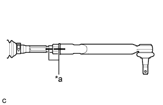
Text in Illustration *a Matchmark Install the lock nut and tie rod assembly LH to the steering rack end sub-assembly until the matchmarks are aligned.
Tech Tips
After adjusting the front wheel alignment, tighten the lock nut.
-
-
CONNECT TIE ROD ASSEMBLY RH
Tech Tips
Perform the same procedure as for the LH side.
-
INSTALL FRONT SPEED SENSOR LH
-
Install the front speed sensor and front flexible hose to the front shock absorber assembly with the bolt and clamp.
- Torque:
- 19 N*m { 192 kgf*cm, 14 ft.*lbf }
Note
Do not twist the front speed sensor when installing it.
Tech Tips
Install the speed sensor harness bracket first and then the front flexible hose.
-
Install the front speed sensor to the steering knuckle with the bolt.
- Torque:
- 8.5 N*m { 87 kgf*cm, 75 in.*lbf }
Note
Do not twist the front speed sensor when installing it.
-
-
INSTALL FRONT SPEED SENSOR RH
Tech Tips
Perform the same procedure as for the LH side.
-
INSTALL FRONT STABILIZER LINK ASSEMBLY LH
-
for Steel Type:
-
Install the front stabilizer link assembly to the front shock absorber assembly with the nut.
- Torque:
- 74 N*m { 755 kgf*cm, 55 ft.*lbf }
If the ball joint turns together with the nut, use a hexagon wrench to hold the stud bolt.
-
-
for Aluminum Type:
-
Install the front stabilizer link assembly to the front shock absorber assembly with the nut.
- Torque:
- for TMC, TMMR Made
- 74 N*m { 755 kgf*cm, 55 ft.*lbf }
- for TMMK Made
- 125 N*m { 1275 kgf*cm, 92 ft.*lbf }
If the ball joint turns together with the nut, use a wrench to hold the stud bolt.
-
-
-
INSTALL FRONT STABILIZER LINK ASSEMBLY RH
Tech Tips
Perform the same procedure as for the LH side.
-
INSTALL FRONT AXLE SHAFT NUT LH
-
Clean the threaded parts on the front drive shaft assembly and a new axle shaft nut using a non-residue solvent.
Note
-
Be sure to perform this work even when using a new drive shaft.
-
Keep the threaded parts free of oil and foreign matter.
-
-
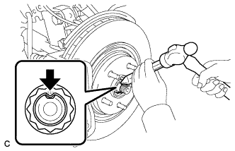
Using a socket wrench (30 mm), install the front axle shaft nut.
- Torque:
- 294 N*m { 2998 kgf*cm, 217 ft.*lbf }
-
Using a chisel and a hammer, stake the front axle shaft nut.
-
-
INSTALL FRONT AXLE SHAFT NUT RH
Tech Tips
Perform the same procedure as for the LH side.
-
CONNECT STEERING INTERMEDIATE SHAFT ASSEMBLY
-
Text in Illustration *a Matchmark Align the matchmarks and install the steering intermediate shaft to the steering link assembly.
-
Install the bolt.
- Torque:
- 35 N*m { 360 kgf*cm, 26 ft.*lbf }
-
-
INSTALL FRONT EXHAUST PIPE ASSEMBLY
-
Install 3 new gaskets to the front exhaust pipe assembly.
-
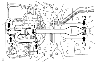
Text in Illustration *1 Bolt *2 Nut *3 Bolt and Nut Install the front exhaust pipe assembly with the 4 bolts and 4 nuts.
- Torque:
- Bolt
- 55 N*m { 561 kgf*cm, 40 ft.*lbf }
- Nut
- 55 N*m { 561 kgf*cm, 40 ft.*lbf }
- Bolt and Nut (for TMC Made)
- 43 N*m { 438 kgf*cm, 32 ft.*lbf }
- Bolt and Nut (for TMMR Made)
- 49 N*m { 500 kgf*cm, 36 ft.*lbf }
-
Install the No. 1 exhaust pipe support bracket with the 2 bolts (for Rear Side).
- Torque:
- 33 N*m { 337 kgf*cm, 24 ft.*lbf }
-
Connect the 2 heated oxygen sensor connectors.
-
Install the 2 wire harnesses to the clamp.
-
-
INSTALL NO. 1 EXHAUST PIPE SUPPORT BRACKET
-
Install the No. 1 exhaust pipe support bracket with the 2 nuts (for Front Side).
- Torque:
- 33 N*m { 337 kgf*cm, 24 ft.*lbf }
-
-
CONNECT NO. 1 COOLER REFRIGERANT SUCTION HOSE
-
Remove the vinyl tape from the No. 1 cooler refrigerant suction hose and compressor and magnetic clutch.
-
Sufficiently apply compressor oil to a new O-ring and the fitting surface of the compressor and magnetic clutch.
Compressor Oil ND-OIL 8 or equivalent -
Install the O-ring to the No. 1 cooler refrigerant suction hose.
-
Connect the No. 1 cooler refrigerant suction hose to the compressor and magnetic clutch with the bolt.
- Torque:
- 9.8 N*m { 100 kgf*cm, 87 in.*lbf }
-
-
CONNECT NO. 1 COOLER REFRIGERANT DISCHARGE HOSE
-
Remove the vinyl tape from the No. 1 cooler refrigerant discharge hose and compressor and magnetic clutch.
-
Sufficiently apply compressor oil to a new O-ring and the fitting surface of the compressor and magnetic clutch.
Compressor Oil ND-OIL 8 or equivalent -
Install the O-ring to the No. 1 cooler refrigerant discharge hose.
-
Connect the No. 1 cooler refrigerant discharge hose to the compressor and magnetic clutch with the bolt.
- Torque:
- 9.8 N*m { 100 kgf*cm, 87 in.*lbf }
-
Engage the 2 clamps and connect the 3 connectors.
-
-
CONNECT FUEL MAIN TUBE
-
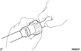
Push in the fuel tube connector to the fuel main tube until the fuel tube connector makes a "click" sound.
Note
-
Check that there is no damage or foreign objects on the fuel tube connector.
-
After connecting, check that the fuel tube connector and the pipe are securely connected by pulling on them.
-
-
Install the No. 1 fuel pipe clamp.
Tech Tips
The half connection prevention connector prevents the fuel hose connector cover from being locked if the fuel tube is not securely connected.
-
-
CONNECT TRANSMISSION CONTROL CABLE ASSEMBLY
-
Connect the transmission control cable assembly to the transmission control cable bracket with a new clip.
-
Connect the transmission control cable assembly to the transmission control shaft lever with the nut.
- Torque:
- 13 N*m { 130 kgf*cm, 9 ft.*lbf }
Note
Before connecting the transmission control cable assembly, check that the park/neutral position switch and the shift lever are in neutral.
-
-
INSTALL AIR CLEANER BRACKET
-
Install the air cleaner bracket to the battery carrier with the bolt.
- Torque:
- 8.0 N*m { 82 kgf*cm, 71 in.*lbf }
-
Connect the 2 wire clamps.
-
-
CONNECT ENGINE WIRE
-
Connect the 2 wire clamps.
-
Connect the connector to the ECM with the lock lever.
-
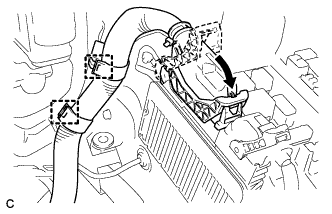
Connect the engine wire to the engine room relay block.
-
Connect the 4 connectors.
-
Connect the engine wire to the engine room relay block.
-
Connect the wire clamp and install the 2 nuts.
- Torque:
- 8.0 N*m { 82 kgf*cm, 71 in.*lbf }
-
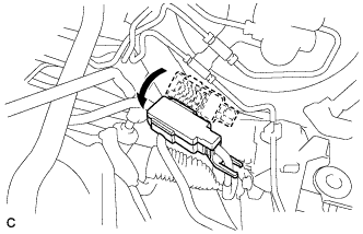
Install the No. 1 relay block cover.
-
-
INSTALL STARTER ASSEMBLY
-
Install the starter assembly with the 2 bolts.
- Torque:
- 37 N*m { 377 kgf*cm, 27 ft.*lbf }
-
Connect the starter connector.
-
Install the terminal nut and cover the nut with the cap.
- Torque:
- 9.8 N*m { 100 kgf*cm, 87 in.*lbf }
-
-
CONNECT OUTLET HEATER WATER HOSE
-
Connect the outlet heater water hose with the hose clip.
-
-
CONNECT INLET HEATER WATER HOSE
-
Connect the inlet heater water hose with the hose clip.
-
-
CONNECT INLET NO. 1 OIL COOLER HOSE
-
Connect the inlet No. 1 oil cooler hose to the automatic transaxle assembly with the hose clip.
-
-
CONNECT OUTLET NO. 1 OIL COOLER HOSE
-
Connect the outlet No. 1 oil cooler hose to the automatic transaxle assembly with the hose clip.
-
-
CONNECT NO. 2 RADIATOR HOSE
-
Connect the No. 2 radiator hose with the hose clip.
-
-
CONNECT NO. 1 RADIATOR HOSE
-
Connect the No. 1 radiator hose with the hose clip.
-
Install the air fuel ratio sensor wire to the No. 1 radiator hose with the hose clamp.
-
-
CONNECT UNION TO CHECK VALVE HOSE
-
Connect the union to check valve hose to the brake booster with the hose clip.
-
-
CONNECT NO. 1 FUEL VAPOR FEED HOSE
-
Connect the No. 1 fuel vapor feed hose with the hose clip.
-
-
CONNECT EARTH WIRE
-
Install the earth wire with the 2 bolts.
- Torque:
- 8.0 N*m { 82 kgf*cm, 71 in.*lbf }
-
-
INSTALL ENGINE MOVING CONTROL ROD
-
Temporarily install the engine moving control rod to the engine moving control rod bracket with the bolt.
Tech Tips
Perform this procedure only when replacement of the engine moving control rod is necessary.
-
-
INSTALL ENGINE MOVING CONTROL ROD BRACKET
-
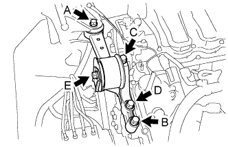
When replacing the engine moving control rod.
-
Install the engine moving control rod bracket with engine moving control rod with the 4 bolts.
- Torque:
- 38 N*m { 387 kgf*cm, 28 ft.*lbf }
Note
Temporarily tighten bolt A and B, and then fully tighten the 4 bolts in the order of C, D, A and B.
-
Tighten the bolt E.
- Torque:
- 52 N*m { 530 kgf*cm, 38 ft.*lbf }
-
-
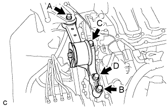
When not replacing the engine moving control rod.
-
Install the engine moving control rod bracket with engine moving control rod with the 4 bolts.
- Torque:
- 38 N*m { 387 kgf*cm, 28 ft.*lbf }
Note
Temporarily tighten bolt A and B, and then fully tighten the 4 bolts in the order of C, D, A and B.
-
-
-
INSTALL NO. 2 ENGINE MOUNTING STAY RH
-
Install the No. 2 engine mounting stay RH with the bolt.
- Torque:
- 38 N*m { 387 kgf*cm, 28 ft.*lbf }
-
Tighten the 2 nuts.
- Torque:
- 23 N*m { 234 kgf*cm, 17 ft.*lbf }
-
-
INSTALL INTAKE AIR RESONATOR SUB-ASSEMBLY
-
Install the intake air resonator sub-assembly with the 2 bolts.
- Torque:
- 8.0 N*m { 82 kgf*cm, 71 in.*lbf }
-
Connect the 2 vacuum hoses and engage the claw.
-
-
INSTALL INLET NO. 1 AIR CLEANER
-
Install the inlet No. 1 air cleaner to the intake air resonator sub-assembly.
-
Engage the pin to the radiator support.
-
-
INSTALL BATTERY
-
Install the battery and battery tray.
-
Install the battery clamp with the bolt and nut.
- Torque:
- Bolt
- 9.0 N*m { 92 kgf*cm, 80 in.*lbf }
- Nut
- 3.5 N*m { 36 kgf*cm, 31 in.*lbf }
-
Connect the positive (+) cable to the positive (+) battery terminal.
- Torque:
- 6.5 N*m { 66 kgf*cm, 58 in.*lbf }
-
-
INSTALL AIR CLEANER CASE SUB-ASSEMBLY
-
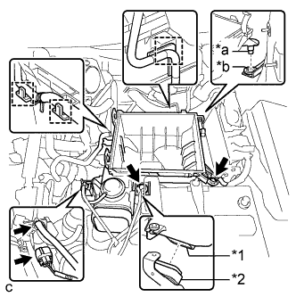
Text in Illustration *1 Air Cleaner Case Sub-assembly *2 Inlet No. 1 Air Cleaner *a Projection *b Hole Install the air cleaner case sub-assembly to the inlet No. 1 air cleaner.
-
Insert the projection of the air cleaner case sub-assembly to the hole of the No. 2 air cleaner bracket as shown in the illustration.
-
Tighten the 2 bolts.
- Torque:
- 5.0 N*m { 51 kgf*cm, 44 in.*lbf }
-
Connect the wire harness clamp, connector, vacuum hose and No. 1 fuel vapor feed hose.
-
-
INSTALL AIR CLEANER FILTER ELEMENT SUB-ASSEMBLY
-
INSTALL AIR CLEANER CAP SUB-ASSEMBLY
-
Connect the air cleaner cap sub-assembly to the throttle with motor body assembly with the hose clamp.
-
Install the air cleaner cap with hose to the air cleaner case with the 2 clamps.
-
Connect the wire harness clamp and mass air flow meter connector.
-
Connect the 3 hoses.
-
Connect the ventilation hose.
-
Connect the mass air flow meter connector and wire harness clamp.
-
-
INSTALL INLET NO. 2 AIR CLEANER
-
Install the inlet No. 2 air cleaner to the air cleaner case sub-assembly with the 2 bolts.
- Torque:
- 8.0 N*m { 82 kgf*cm, 71 in.*lbf }
-
Connect the 2 wire harness clamps and vacuum hose clamp.
-
-
INSPECT VACUUM HOSES
-
Inspect the vacuum hoses.
-
-
CONNECT CABLE TO NEGATIVE BATTERY TERMINAL
Note
When disconnecting the cable, some systems need to be initialized after the cable is reconnected Click here.
-
INSTALL FRONT WHEEL
- Torque:
- 103 N*m { 1049 kgf*cm, 76 ft.*lbf }
-
ADD ENGINE OIL
-
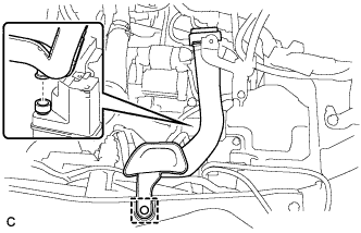
Add clean engine oil and install the oil filler cap.
Note
-
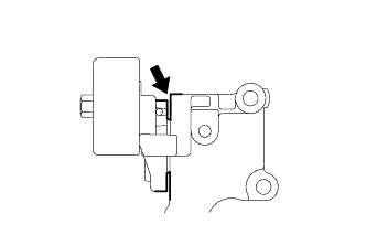
Do not allow engine oil adhere to the moving parts of the belt tensioner, as this may cause malfunctions.
If engine oil is on the location indicated by the arrow, replace the belt tensioner.
Standard Oil Grade Oil Grade Oil Viscosity (SAE)
-
API grade SL "Energy-Conserving", SM "Energy-Conserving", SN "Resource-Conserving" or ILSAC multigrade engine oil
-
0W-20
-
5W-20
-
5W-30
-
10W-30
-
API grade SL, SM or SN multigrade engine oil
-
15W-40
-
20W-50
Standard Capacity Item Standard Condition Drain and refill with oil filter change 6.1 liters (6.4 US qts, 5.4 lmp. qts) Drain and refill without oil filter change 5.7 liters (6.0 US qts, 5.0 lmp. qts) Dry fill 6.8 liters (7.2 US qts, 6.0 lmp. qts) -
-
-
ADD ENGINE COOLANT
-
ADD AUTOMATIC TRANSAXLE FLUID
-
CHARGE AIR CONDITIONING SYSTEM WITH REFRIGERANT
-
Perform vacuum purging using a vacuum pump or appropriate equipment.
-
Charge the air conditioning system with refrigerant.
Refrigerant type HFC-134a (R134a) 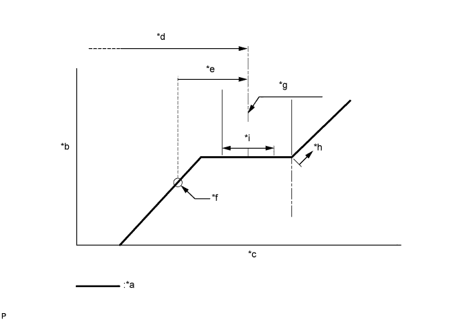
Text in Illustration *a Sub-cool System *b High Pressure *c Refrigerant Amount *d Standard charge amount *e Charge additional 100 g (3.5 oz) *f Point where bubbles disappear *g Mean value in proper range *h Overcharged *i +/-50 g (+/-1.76 oz) - - Standard charge amount 450 to 550 g (15.9 to 19.4 oz) - SST
- 09985-20010 ( 09985-02010, 09985-02050, 09985-02060, 09985-02070, 09985-02080, 09985-02090, 09985-02110, 09985-02130, 09985-02140, 09985-02150 )
Note
-
Do not turn the A/C switch on before charging the air conditioning system with refrigerant. Doing so may cause the compressor to work without refrigerant, resulting in overheating of the compressor.
-
The refrigerant amount should be checked by quantity (weight).
Tech Tips
Ensure that sufficient refrigerant is available to recharge the system when using a refrigerant recovery unit. Refrigerant recovery units are not always able to recover 100% of the refrigerant from an air conditioning system.
-
-
WARM UP ENGINE
-
Keep the A/C switch on for at least 2 minutes to warm up the compressor.
Note
To prevent damage to the compressor, be sure to warm up the compressor when turning the air conditioning on after removing and installing air conditioning system lines (including the compressor).
-
-
INSPECT FOR REFRIGERANT LEAK
-
After recharging the air conditioning system with refrigerant, check for refrigerant leaks using a halogen leak detector.
-
Carry out the test under the following conditions:
-
Turn the engine switch off.
-
Measure the pressure to make sure that there is some refrigerant remaining in the air conditioning system.
Pressure when the compressor is off: approx. 392 to 588 kPa (3.9 to 5.9 kgf/cm2, 57 to 85 psi)
-
Ensure good ventilation (the halogen leak detector may react to volatile gases which are not refrigerant, such as gasoline vapor and exhaust gas).
-
Repeat the inspection 2 or 3 times.
-
-
Remove the front outer cowl top panel sub-assembly Click here for LHD or Click here for RHD).
-
Remove the front bumper assembly Click here.
-
Remove the radiator side deflector RH Click here.
-
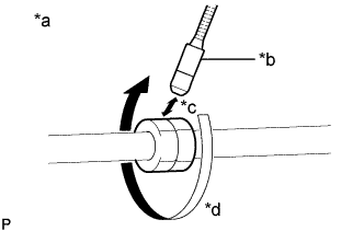
Text in Illustration *a Check for leaks *b Halogen Leak Detector Sensor *c Distance between Sensor and Joint to be Checked:
10 mm or less
*d Halogen Leak Detector Sensor Moving Speed:
25 to 50 mm/sec.
How to check for refrigerant leaks in pipe joints:
Note
Gas leaking from a joint can be dissipated by even the slightest breeze. Move the halogen leak detector sensor 360° around each joint instead of keeping it in one spot when checking.
-
Using a halogen leak detector, check for refrigerant leaks at the pipe joints shown in the illustration.
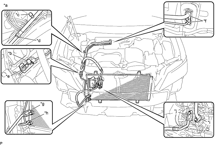
Text in Illustration *a Area to be Checked *b Service Valve (High) *c Service Valve (Low) *d Pipe Joint *e Air Conditioner Pressure Sensor Joint *f Cooler Expansion Valve Joint *g Condenser Joint (Inlet) *h Condenser Joint (Outlet) *i Compressor Joint (Inlet) *j Compressor Joint (Outlet) Tech Tips
-
After the blower motor has stopped, leave the cooling unit for more than 15 minutes.
-
Disconnect the pressure sensor connector and leave it for approximately 20 minutes.
-
When checking for leaks, the presence of oily dirt at a joint can indicate a leak.
Standard There are no refrigerant leaks from the joints. If refrigerant is leaking, disconnect the leaking joint and visually check for the cause, such as the presence of foreign matter.
-
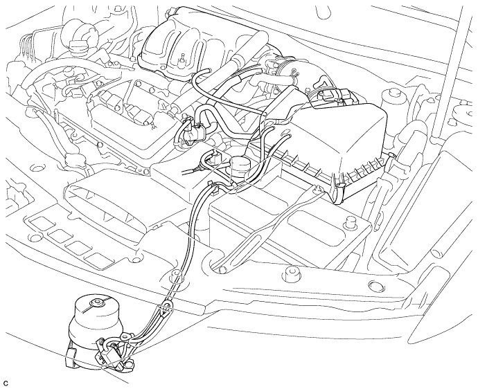
-
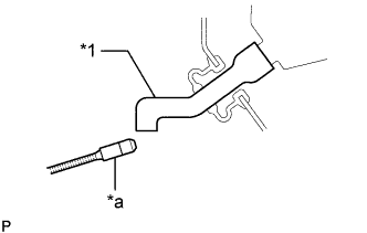
Text in Illustration *1 Drain Cooler Hose *a Halogen Leak Detector Bring the halogen leak detector sensor close to the drain cooler hose with the detector turned off, and then turn the detector on.
Note
Keep water away from the halogen leak detector to prevent malfunction.
Tech Tips
-
After the blower motor has stopped, leave the cooling unit for more than 15 minutes.
-
When bringing the halogen leak detector sensor close to the drain cooler hose, make sure that the halogen leak detector does not react to volatile gases. If it is not possible to avoid interference from volatile gases, the vehicle should be lifted up to allow checking for leaks.
Standard Refrigerant is not leaking from the drain cooler hose. If refrigerant is leaking, check for refrigerant leaks from the No. 1 cooler evaporator sub-assembly.
-
-
Remove the blower motor with fan sub-assembly Click here.
-
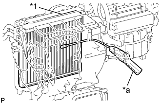
Text in Illustration *1 No. 1 Cooler Evaporator Sub-assembly *a Halogen Leak Detector Insert the halogen leak detector sensor into the air conditioning unit assembly, bring the sensor close to the No. 1 cooler evaporator sub-assembly and check for refrigerant leaks.
Tech Tips
After the blower motor has stopped, leave the cooling unit for more than 15 minutes.
Standard Refrigerant is not leaking from the No. 1 cooler evaporator sub-assembly. If refrigerant is leaking, disconnect the leaking joint and visually check for the cause, such as the presence of foreign matter.
-
Install the blower motor with fan sub-assembly Click here.
-
Install the radiator side deflector RH Click here.
-
Install the front bumper assembly Click here.
-
Install the front outer cowl top panel sub-assembly Click here for LHD or Click here for RHD).
-
-
INSPECT ENGINE OIL LEVEL
-
Warm up the engine, stop it and wait 5 minutes. The oil level should be between the engine oil level dipstick low level mark and full level mark.
If the engine oil level is low, check for leakage and add oil up to the full level mark.
Note
Do not add engine oil to above the full level mark.
-
-
INSPECT ENGINE COOLANT LEVEL IN RESERVOIR
-
Check that the engine coolant level is between the low and full lines when the engine is cold.
If the engine coolant level is low, check for leaks and add "TOYOTA Super Long Life Coolant" or similar high quality ethylene glycol based non-silicate, non-amine, non-nitrite and non-borate coolant with long-life hybrid organic acid technology to the full line.
Note
Do not substitute plain water for engine coolant.
-
-
INSPECT FOR FUEL LEAK
-
Check fuel pump operation.
-
Connect the intelligent tester to the DLC3.
-
Turn the engine switch on (IG) and turn the intelligent tester on.
Note
Do not start the engine.
-
Enter the following menus: Powertrain / Engine / Active Test / Control the Fuel Pump / Speed.
-
Check for pressure in the fuel inlet tube from the fuel line. Check that sounds of fuel flowing from the fuel tank can be heard. If no sounds can be heard, check the integration relay, fuel pump, fuel pump control ECU, ECM and wiring connectors.
-
-
Inspect for fuel leaks.
-
Check that there are no fuel leaks from the fuel system after doing any maintenance or repairs. If there is a fuel leak, repair or replace parts as necessary.
-
-
Turn the engine switch off.
-
Disconnect the intelligent tester from the DLC3.
-
-
INSPECT FOR COOLANT LEAK
CAUTION:
Do not remove the radiator cap sub-assembly while the engine and radiator are still hot. Pressurized, hot engine coolant and steam may be released and cause serious burns.
Note
Before performing each inspection, turn the A/C switch OFF.
-
Fill the radiator with coolant and attach a radiator cap tester.
-
Warm up the engine.
-
Using a radiator cap tester, increase the pressure inside the radiator to 118 kPa (1.2 kgf*cm, 17 psi), and check that the pressure does not drop.
If the pressure drops, check the hoses, radiator and water pump for leaks. If no external leaks are found, check the heater core, cylinder block and cylinder head.
-
-
INSPECT FOR OIL LEAK
-
INSPECT FOR EXHAUST GAS LEAK
-
INSPECT IGNITION TIMING
-
Warm up and stop the engine.
Tech Tips
A warmed up engine should have an engine coolant temperature of over 80°C (176°F), an engine oil temperature of 60°C (140°F), and the engine speed should be stabilized.
-
When using the intelligent tester:
Check the ignition timing.
-
Connect the intelligent tester to the DLC3.
-
Start the engine and run it at idle.
-
Turn the intelligent tester main switch on.
-
Enter the following menus: Powertrain / Engine / Data List / IGN Advance.
Standard ignition timing 9.5 to 24.5° BTDC at idle Note
-
Check the ignition timing with the cooling fans off.
-
Turn off all electrical systems and the A/C.
-
When checking the ignition timing, the transaxle should be in neutral or park.
Tech Tips
Refer to the intelligent tester operator's manual for further details.
-
-
Check that the ignition timing advances immediately when the engine speed is increased.
-
Enter the following menus: Powertrain / Engine / Active Test / Connect the TC and TE1.
-
Monitor IGN Advance.
-
Perform the Active Test.
Standard ignition timing 8 to 12° BTDC at idle Note
When checking the ignition timing, the transaxle should be in neutral or park.
Tech Tips
Refer to the intelligent tester operator's manual for further details.
-
-
When not using the intelligent tester:
-
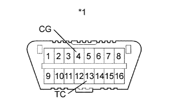
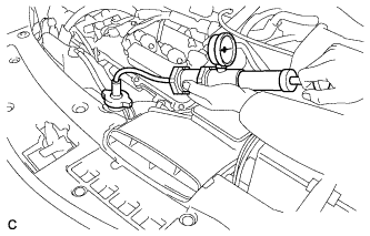
Text in Illustration *1 DLC3 Using SST, connect terminals 13 (TC) and 4 (CG) of the DLC3.
- SST
- 09843-18040
Note
-
Confirm the terminals before connecting them. Connecting the wrong terminals may result in damage to electrical components.
-
Check the ignition timing with the cooling fans off.
-
Turn off all the electrical systems and the A/C.
-
When checking the ignition timing, the transaxle should be in neutral or park.
-
Remove the V-bank cover sub-assembly Click here.
-
Connect the timing light tester probe to the ignition coil wire for No. 1 cylinder.
Note
Use a timing light that detects primary signals.
-
Check the ignition timing at idle.
Standard ignition timing 8 to 12° BTDC at idle Note
When checking the ignition timing, the transaxle should be in neutral or park.
Tech Tips
Run the engine at 1000 to 1300 rpm for 5 seconds, and then check that the engine rpm returns to idle speed.
-
Disconnect terminals 13 (TC) and 4 (CG) of the DLC3.
-
Check the ignition timing at idle.
Standard ignition timing 9.5 to 24.5° BTDC at idle -
Confirm that the ignition timing advances immediately when the engine rpm is increased.
-
Remove the timing light from the engine.
-
Install the V-bank cover sub-assembly Click here.
-
-
-
INSPECT ENGINE IDLE SPEED
-
Warm up and stop the engine.
Tech Tips
A warmed up engine should have an engine coolant temperature of over 80°C (176°F), an engine oil temperature of 60°C (140°F), and the engine speed should be stabilized.
-
When using the intelligent tester:
Check the idle speed.
-
Connect the intelligent tester to the DLC3.
-
Start the engine and run it at idle.
-
Turn the intelligent tester main switch on.
-
Enter the following menus: Powertrain / Engine / Data List / Engine Speed.
-
Read the value displayed on the tester.
Standard idle speed 600 to 700 rpm Note
-
Check the idle speed with the cooling fans off.
-
Turn off all the electrical systems and the A/C.
-
When checking the idle speed, the transaxle should be in neutral or park.
Tech Tips
-
Refer to the intelligent tester operator's manual for further details.
-
If the speed is not as specified, check the air intake system.
-
-
-
When not using the intelligent tester:
-
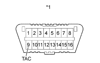
Text in Illustration *1 DLC3 Using SST, connect a tachometer probe to terminal 9 (TAC) of the DLC3.
- SST
- 09843-18030
-
Check the idle speed.
Standard idle speed 600 to 700 rpm Note
-
Check the idle speed with the cooling fans off.
-
Turn off all the electrical systems and the A/C.
-
When checking the idle speed, the transaxle should be in neutral or park.
Tech Tips
If the speed is not as specified, check the air intake system.
-
-
-
-
INSPECT CO/HC
Tech Tips
This check determines whether or not the idle CO/HC complies with regulations.
-
Start the engine.
-
Keep the engine speed at 2500 rpm for approximately 180 seconds.
-
Insert the CO/HC meter testing probe at least 40 cm (1.31 ft.) into the tailpipe during idle.
-
Immediately check CO/HC concentration during idle and when running at 2500 rpm.
Tech Tips
When performing the 2 mode (with the engine idling/running at 2500 rpm) test, follow the measurement order determined by applicable local regulations.
If the CO/HC concentration does not comply with the regulations, perform troubleshooting in the order given below.
-
Check the DTCs Click here.
-
See the table below for possible causes, then inspect and correct the applicable causes if necessary.
CO HC Problem Cause Normal High Rough idle
-
Faulty ignition:
-
Incorrect valve timing
-
Fouled, shorted or improperly gapped plugs
-
Incorrect valve clearance (valve lash adjuster)
-
Leaks in intake or exhaust valves
-
Leaks in cylinders
Low High Rough idle
(Fluctuating HC reading)
-
Vacuum leaks:
-
PCV hoses
-
Intake manifold
-
Throttle body assembly
-
Brake booster line
-
Lean mixture causing misfire
High High Rough idle
(Black smoke from exhaust)
-
Restricted air cleaner filter element sub-assembly
-
Plugged PCV valve
-
Faulty SFI system:
-
Faulty fuel pressure regulator
-
Defective engine coolant temperature sensor
-
Defective mass air flow meter
-
Faulty ECM
-
Faulty injector assemblies
-
Faulty throttle position sensor (built in throttle body assembly)
-
-
-
-
CHECK FOR SPEED SENSOR SIGNAL
-
INSPECT SHIFT LEVER POSITION
-
When the shift lever is moved from P to R with the engine switch on (IG) and brake pedal depressed, make sure that the shift lever moves smoothly and correctly the position.
-
Start the engine and make sure that the vehicle moves forward when the shift lever is moved from N to D and moves rearward when the shift lever is moved to R.
-
-
ADJUST SHIFT LEVER POSITION
-
Move the shift lever to N.
-
Remove the console box Click here.
-
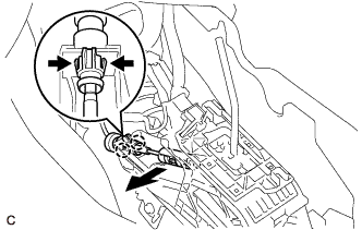
Disconnect the end of the transmission control cable assembly from the lower shift lever assembly
-
Disengage the 2 claws and disconnect the transmission control cable assembly from the lower shift lever assembly.
-
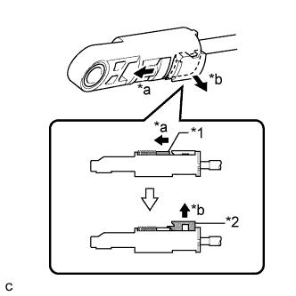
Text in Illustration *1 Slider *2 Lock Piece *a Slide *b Pull Slide the slider of the transmission control cable assembly as shown in the illustration and pull the lock piece outward.
-
Engage the 2 claws to connect the transmission control cable assembly to the lower shift lever assembly.
-
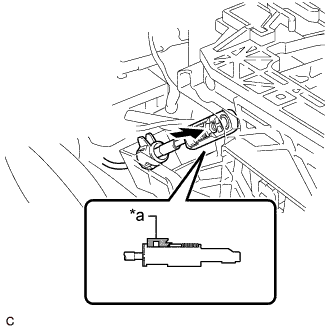
Text in Illustration *a Lock Piece Connect the end of the transmission control cable assembly to the lower shift lever assembly.
Note
-
Check that the lock piece is pulled out.
-
Push the end of the transmission control cable assembly all the way to the base of the lower shift lever assembly pin.
-
-
Push the lock piece into the adjuster case.
Note
-
Check that the park/neutral position switch assembly and the shift lever are in neutral.
-
Securely push in the lock piece until the slider lock is engaged.
-
-
After adjusting the shift lever position, check the operation and function of the shift lever. If there is a problem, adjust the position again.
-
Install the console box Click here.
-
-
INSPECT AND ADJUST FRONT WHEEL ALIGNMENT
-
INSTALL V-BANK COVER SUB-ASSEMBLY
-
Fit the 3 retainers and install the V-bank cover sub-assembly.
-
-
INSTALL COOL AIR INTAKE DUCT SEAL
-
INSTALL FRONT FENDER APRON SEAL LH
-
INSTALL ENGINE UNDER COVER LH
-
INSTALL FRONT WHEEL OPENING EXTENSION PAD LH
-
INSTALL FRONT FENDER APRON SEAL RH
-
INSTALL FRONT WHEEL OPENING EXTENSION PAD RH
-
INSTALL ENGINE UNDER COVER RH