AUTOMATIC TRANSAXLE UNIT REASSEMBLY

Tech Tips
Check each bearing position and installation direction.
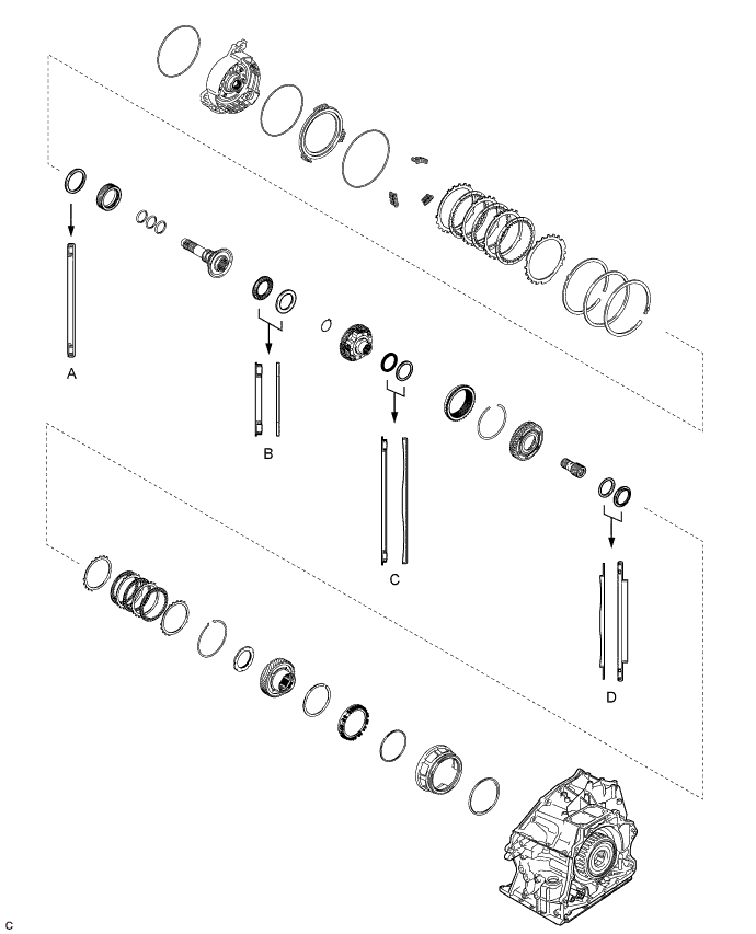
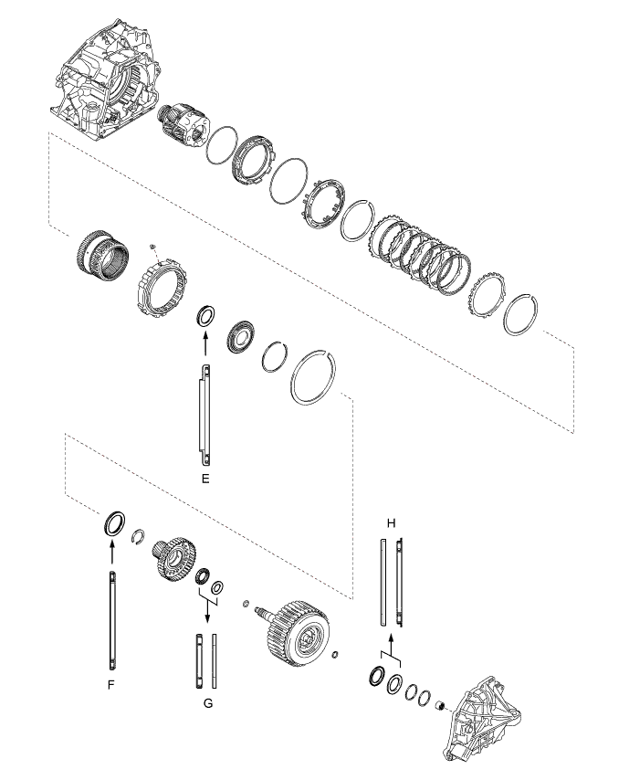
| Mark | Front Race Diameter Inside / Outside (mm (in.)) |
Thrust Bearing Diameter Inside / Outside (mm (in.)) |
Rear Race Diameter Inside / Outside (mm (in.)) |
|---|---|---|---|
| A | - | 57.7 (2.27) / 75.2 (2.96) | - |
| B | - | 29.1 (1.15) / 48.6 (1.91) | 30.7 (1.21) / 48.3 (1.90) |
| C | - | 62.6 (2.46) / 82.4 (3.24) | 65.9 (2.59) / 82.3 (3.24) |
| D | 59.4 (2.34) / 76 (2.99) | 53.46 (2.10) / 79 (3.11) | - |
| E | - | 56.1 (2.21) / 81.1 (3.19) | - |
| F | - | 61.2 (2.41) / 79 (3.11) | - |
| G | - | 28 (1.10) / 47.1 (1.85) | 26.1 (1.03) / 44 (1.73) |
| H | 52.2 (2.06) / 70.4 (2.77) | 48.9 (1.93) / 72.0 (2.83) | - |
-
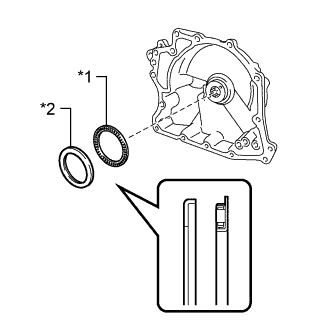
INSTALL COUNTER DRIVE GEAR BEARING
Note
Perform this procedure only when replacement of the counter drive gear bearing or transaxle case sub-assembly is necessary.
-
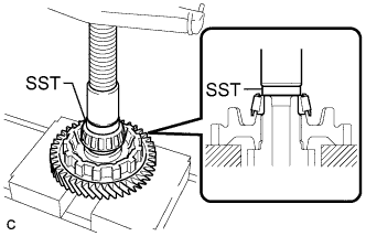
Using SST and a press, install a new counter drive gear bearing (outer race) and snap ring to the transaxle case sub-assembly.
- SST
- 09950-60020 ( 09951-01030 )
- 09950-70010 ( 09951-07100 )
-
-
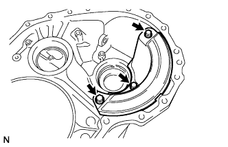
INSTALL FRONT DIFFERENTIAL CASE REAR TAPERED ROLLER BEARING (OUTER RACE)
-
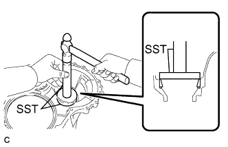
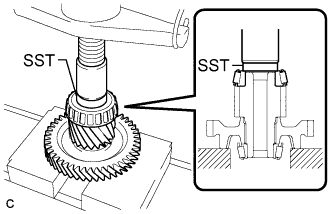
Using SST and a hammer, install a new front differential case rear tapered roller bearing (outer race) to the transaxle case sub-assembly.
- SST
- 09950-60020 ( 09951-00810 )
- 09950-70010 ( 09951-07150 )
Note
Make sure to install the front differential case rear tapered roller bearing (outer race) so that there is no clearance between the front differential case rear tapered roller bearing (outer race) and transaxle case sub-assembly.
-
-
INSTALL FRONT DIFFERENTIAL CASE FRONT TAPERED ROLLER BEARING (OUTER RACE)
-
Install the shim to the transaxle housing.
-
Using SST and a hammer, install a new front differential case front tapered roller bearing (outer race) to the transaxle housing.
- SST
- 09950-60020 ( 09951-00790 )
- 09950-70010 ( 09951-07150 )
Note
Make sure to install the front differential case front tapered roller bearing (outer race) so that there is no clearance between the front differential case front tapered roller bearing (outer race), shim and transaxle housing.
-
-
INSTALL FRONT DIFFERENTIAL CASE REAR TAPERED ROLLER BEARING (INNER RACE)
-
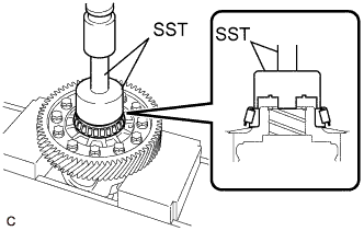
Using SST and a press, install a new front differential case rear tapered roller bearing (inner race) to the front differential case.
- SST
- 09726-36010
- 09950-70010 ( 09951-07100 )
Note
-
Do not damage the front differential case rear tapered roller bearing (inner race) cage when installing the front differential case rear tapered roller bearing (inner race).
-
Make sure to install the front differential case rear tapered roller bearing (inner race) so that there is no clearance between the front differential case rear tapered roller bearing (inner race) and front differential case.
-
-
INSTALL FRONT DIFFERENTIAL CASE FRONT TAPERED ROLLER BEARING (INNER RACE)
-
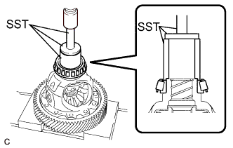
Using SST and a press, install a new front differential case front tapered roller bearing (inner race) to the front differential case.
- SST
- 09523-36010
- 09950-60010 ( 09951-00540 )
- 09950-70010 ( 09951-07100 )
Note
-
Do not damage the front differential case front tapered roller bearing (inner race) cage when installing the front differential case front tapered roller bearing (inner race).
-
Make sure to install the front differential case front tapered roller bearing (inner race) so that there is no clearance between the front differential case front tapered roller bearing (inner race) and front differential case.
-
-
ADJUST DIFFERENTIAL SIDE BEARING PRELOAD
-
Remove any remaining seal packing from the contact surfaces of the transaxle housing and transaxle case sub-assembly.
-
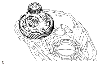
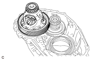
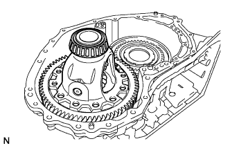
Install the front differential case to the transaxle case sub-assembly.
-
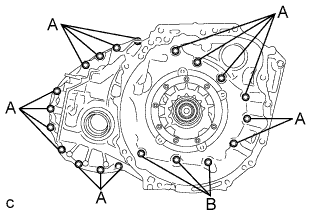
Install the transaxle housing to the transaxle case sub-assembly with the 20 bolts.
- Torque:
- Bolt (A)
- 30.6 N*m { 312 kgf*cm, 23 ft.*lbf }
- Bolt (B)
- 22.7 N*m { 231 kgf*cm, 17 ft.*lbf }
-
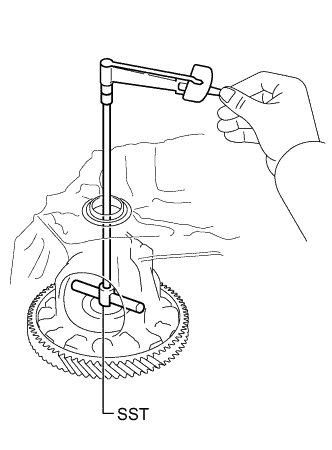
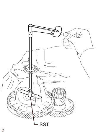
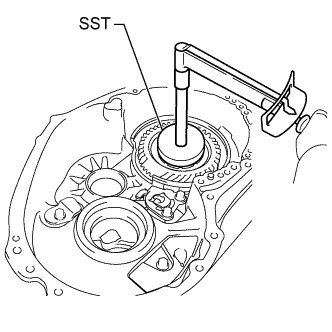
Using SST, turn the front differential case right and left 2 or 3 times to settle the bearings.
- SST
- 09564-33010
-
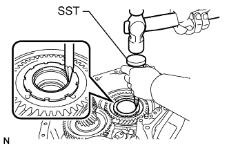
Using SST and a torque wrench, measure the turning torque of the differential side bearings while rotating SST at 10 rpm.
- SST
- 09564-33010
Turning Torque 1.3 to 1.7 N*m (13 to 17 kgf*cm, 12 to 15 in.*lbf) If the turning torque is not within the specified range, refer to the table below to select a shim for the front differential case front tapered roller bearing (outer race) so that the turning torque is within the specified range.
Shim Thickness Part No. Thickness
(mm (in.))
90564-69001 2.000 (0.0787) 90564-69002 2.025 (0.0797) 90564-69003 2.050 (0.0807) 90564-69004 2.075 (0.0817) 90564-69005 2.100 (0.0827) 90564-69006 2.125 (0.0837) 90564-69007 2.150 (0.0846) 90564-69008 2.175 (0.0856) 90564-69009 2.200 (0.0866) 90564-69010 2.225 (0.0876) 90564-69011 2.250 (0.0886) 90564-69012 2.275 (0.0896) 90564-69013 2.300 (0.0906) 90564-69014 2.325 (0.0915) 90564-69015 2.350 (0.0925) 90564-69016 2.375 (0.0935) 90564-69017 2.400 (0.0945) 90564-69020 2.425 (0.0955) 90564-69021 2.450 (0.0965) 90564-69022 2.475 (0.0974) 90564-69023 2.500 (0.0984) 90564-69024 2.525 (0.0994) 90564-69025 2.550 (0.100) 90564-69026 2.575 (0.101) 90564-69027 2.600 (0.102) 90564-69028 2.625 (0.103) 90564-69029 2.650 (0.104) 90564-69030 2.675 (0.105) 90564-69031 2.700 (0.106) 90564-69032 2.725 (0.107) 90564-69033 2.750 (0.108) 90564-69034 2.775 (0.109) 90564-69035 2.800 (0.110) 90564-69036 2.825 (0.111) 90564-69037 2.850 (0.112) 90564-69038 2.875 (0.113) -
Remove the 20 bolts and transaxle housing from the transaxle case sub-assembly.
-
Remove the front differential case from the transaxle case sub-assembly.
-
-
INSTALL DIFFERENTIAL DRIVE PINION TAPERED ROLLER BEARING LH (OUTER RACE)
-
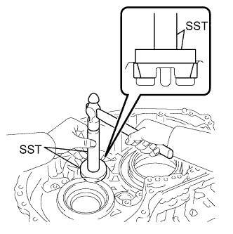
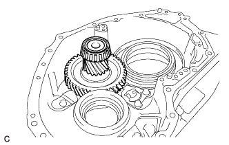
Using SST and a hammer, install a new differential drive pinion tapered roller bearing LH (outer race) to the transaxle case sub-assembly.
- SST
- 09950-60010 ( 09951-00630 )
- 09950-70010 ( 09951-07100 )
Note
Make sure to install the differential drive pinion tapered roller bearing LH (outer race) so that there is no clearance between the differential drive pinion tapered roller bearing LH (outer race) and transaxle case sub-assembly. If there is any clearance, the turning torque of the counter driven gear cannot be measured correctly.
-
-
INSTALL DIFFERENTIAL DRIVE PINION TAPERED ROLLER BEARING RH (OUTER RACE)
-
Install the shim to the transaxle housing.
-
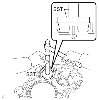
Using SST, install a new differential drive pinion tapered roller bearing RH (outer race) to the transaxle housing.
- SST
- 09950-60020 ( 09951-00710 )
- 09950-70010 ( 09951-07100 )
Note
Make sure to install the differential drive pinion tapered roller bearing RH (outer race) so that there is no clearance between the differential drive pinion tapered roller bearing RH (outer race), shim and transaxle housing. If there is any clearance, the turning torque of the counter driven gear cannot be measured correctly.
-
-
INSTALL DIFFERENTIAL DRIVE PINION TAPERED ROLLER BEARING LH (INNER RACE)
-
Using SST and a press, install a new differential drive pinion tapered roller bearing LH (inner race) to the counter driven gear.
- SST
- 09950-60010 ( 09951-00400 )
Note
Make sure to install the differential drive pinion tapered roller bearing LH (inner race) so that there is no clearance between the differential drive pinion tapered roller bearing LH (inner race) and counter driven gear. If there is any clearance, the turning torque of the counter driven gear cannot be measured correctly.
-
-
INSTALL DIFFERENTIAL DRIVE PINION TAPERED ROLLER BEARING RH (INNER RACE)
-
Using SST and a press, install a new differential drive pinion tapered roller bearing RH (inner race) to the counter driven gear.
- SST
- 09950-60010 ( 09951-00490 )
Note
Make sure to install the differential drive pinion tapered roller bearing RH (inner race) so that there is no clearance between the differential drive pinion tapered roller bearing RH (inner race) and counter driven gear. If there is any clearance, the turning torque of the counter driven gear cannot be measured correctly.
-
-
ADJUST COUNTER DRIVEN GEAR PRELOAD
-
Remove any remaining seal packing from the contact surfaces of the transaxle housing and transaxle case sub-assembly.
-
Install the counter driven gear to the transaxle case sub-assembly.
-
Install the front differential case to the transaxle case sub-assembly.
-
Install the transaxle housing to the transaxle case sub-assembly with the 20 bolts.
- Torque:
- Bolt (A)
- 30.6 N*m { 312 kgf*cm, 23 ft.*lbf }
- Bolt (B)
- 22.7 N*m { 231 kgf*cm, 17 ft.*lbf }
-
Using SST and a torque wrench, measure the turning torque of the counter driven gear while rotating SST at 10 rpm.
- SST
- 09564-33010
Turning Torque Differential side bearing preload + 2.9 to 6.1 N*m (30 to 62 kgf*cm, 26 to 54 in.*lbf) If the turning torque is not within the specified range, refer to the table below to select a shim for the differential drive pinion tapered roller bearing RH (outer race) so that the turning torque is within the specified range.
Shim Thickness Part No. Thickness
(mm (in.))
90564-61022 2.000 (0.0787) 90564-61023 2.025 (0.0797) 90564-61024 2.050 (0.0807) 90564-61025 2.075 (0.0817) 90564-61026 2.100 (0.0827) 90564-61027 2.125 (0.0837) 90564-61028 2.150 (0.0846) 90564-61029 2.175 (0.0856) 90564-61030 2.200 (0.0866) 90564-61031 2.225 (0.0876) 90564-61032 2.250 (0.0886) 90564-61033 2.275 (0.0896) 90564-61034 2.300 (0.0906) 90564-61035 2.325 (0.0915) 90564-61036 2.350 (0.0925) 90564-61037 2.375 (0.0935) 90564-61038 2.400 (0.0945) 90564-61039 2.425 (0.0955) 90564-61040 2.450 (0.0965) 90564-61041 2.475 (0.0974) 90564-61042 2.500 (0.0984) 90564-61043 2.525 (0.0994) 90564-61044 2.550 (0.100) 90564-61045 2.575 (0.101) 90564-61046 2.600 (0.102) 90564-61047 2.625 (0.103) 90564-61048 2.650 (0.104) 90564-69049 2.675 (0.105) 90564-61050 2.700 (0.106) 90564-61051 2.725 (0.107) 90564-61052 2.750 (0.108) 90564-61053 2.775 (0.109) 90564-61054 2.800 (0.110) 90564-61055 2.825 (0.111) 90564-61056 2.850 (0.112) 90564-61057 2.875 (0.113) 90564-61058 2.900 (0.114) 90564-61059 2.925 (0.115) 90564-61060 2.950 (0.116) 90564-61061 2.975 (0.117) 90564-61062 3.000 (0.118) -
Remove the 20 bolts and transaxle housing from the transaxle case sub-assembly.
-
Remove the front differential case from the transaxle case sub-assembly.
-
Remove the counter driven gear from the transaxle case sub-assembly.
-
-
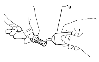
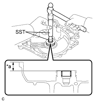
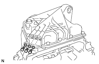
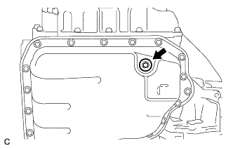
INSTALL MANUAL VALVE LEVER SHAFT OIL SEAL
-
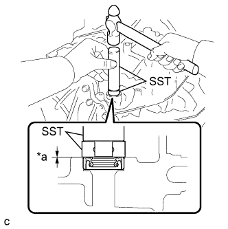
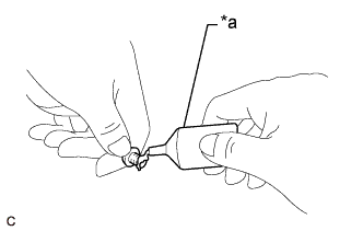
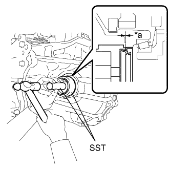
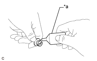
Text in Illustration *a Depth Coat the lip of a new manual valve lever shaft oil seal with a small amount of MP grease.
-
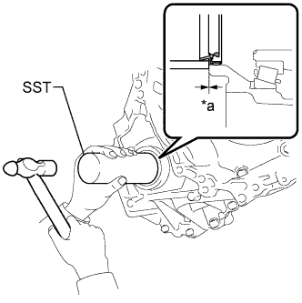
Using SST and a hammer, install the manual valve lever shaft oil seal to the transaxle case sub-assembly.
- SST
- 09950-60010 ( 09951-00230 )
- 09950-70010 ( 09951-07100 )
Standard Depth -0.5 to 0.5 mm (-0.0197 to 0.0197 in.) Note
Make sure the manual valve lever shaft oil seal is installed in the correct direction.
-
-
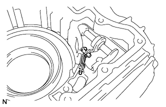
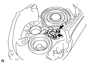
INSTALL MANUAL VALVE LEVER SHAFT SUB-ASSEMBLY
-
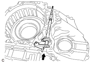
Install the manual valve lever shaft sub-assembly to the transaxle case sub-assembly.
Note
Do not damage the manual valve lever shaft oil seal when installing the manual valve lever shaft sub-assembly to the transaxle case sub-assembly.
-
Using needle-nose pliers, install the manual valve lever shaft retainer spring to the manual valve lever shaft sub-assembly.
-
-
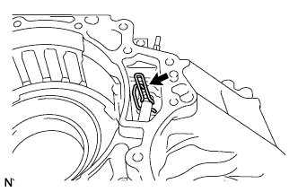
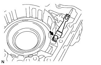
INSTALL PARKING LOCK ROD SUB-ASSEMBLY
-
Align the protrusions on the parking lock rod sub-assembly with the notches on the manual valve lever shaft sub-assembly and install the parking lock rod sub-assembly.
-
-
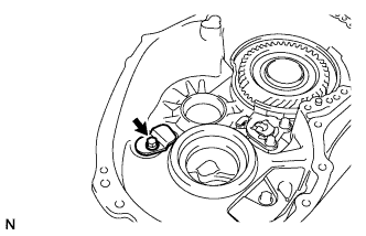
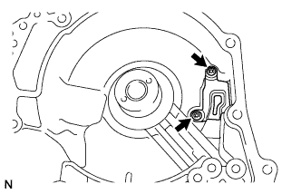
INSTALL MANUAL DETENT SPRING SUB-ASSEMBLY
-
Install the manual detent spring sub-assembly and manual detent spring cover to the transaxle case sub-assembly with the bolt.
- Torque:
- 22.7 N*m { 231 kgf*cm, 17 ft.*lbf }
Note
Make sure to install the manual detent spring sub-assembly first and then the manual detent spring cover.
-
-
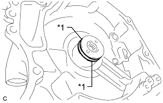
INSTALL NO. 3 BRAKE PISTON
-
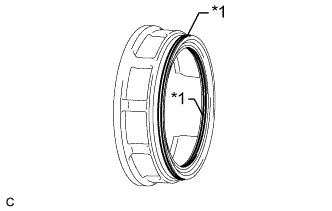
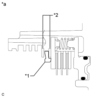
Text in Illustration *1 O-ring Coat 2 new O-rings with ATF and install them to the No. 3 brake piston.
Note
Ensure that the 2 O-rings are not twisted.
-
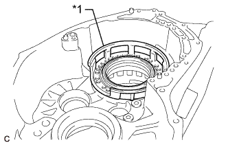
Text in Illustration *1 No. 3 Brake Piston Temporarily install the No. 3 brake piston to the transaxle case sub-assembly.
-
Text in Illustration *1 No. 3 Brake Piston *2 Pawl Stopper Plate Temporarily install the pawl stopper plate to the transaxle case sub-assembly with the 2 bolts.
Note
After installing, make sure that the protrusions on the No. 3 brake piston and grooves on the pawl stopper plate are aligned.
-
Press the No. 3 brake piston into the transaxle case sub-assembly.
Note
Make sure that the O-rings of the No. 3 brake piston are not twisted or caught on the transaxle case sub-assembly.
Tech Tips
Use the installation surface of the No. 3 brake piston return spring sub-assembly to press the No. 3 brake piston into the transaxle case sub-assembly.
-
Remove the 2 bolts and pawl stopper plate from the transaxle case sub-assembly.
-
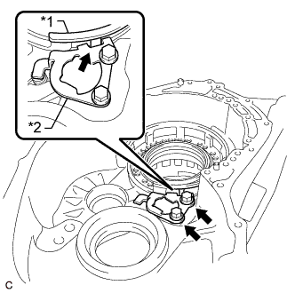
Text in Illustration *1 No. 3 Brake Piston *2 No. 3 Brake Piston Return Spring Sub-assembly Install the No. 3 brake piston return spring sub-assembly to the transaxle case sub-assembly.
Note
Install the No. 3 brake piston return spring sub-assembly as shown in the illustration.
-
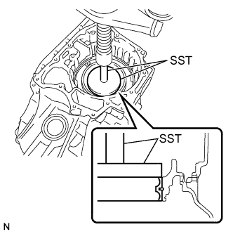
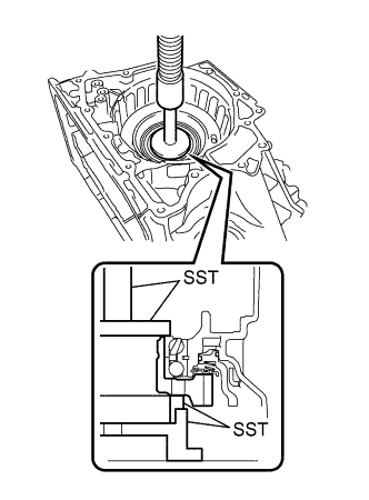
Place SST on the No. 3 brake piston return spring sub-assembly and compress the No. 3 brake piston return spring sub-assembly with a press.
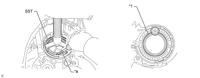
Text in Illustration *1 Snap Ring - - *a Protective Tape - - - SST
- 09387-00070
Note
Stop the press when the No. 3 brake piston return spring sub-assembly is flush with the snap ring groove. This prevents the No. 3 brake piston return spring sub-assembly from being deformed.
-
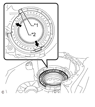
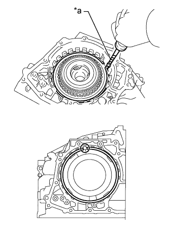
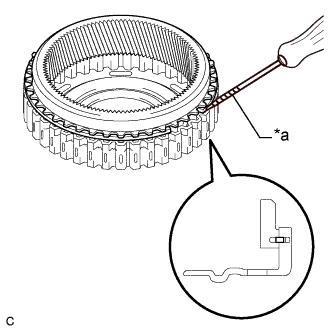
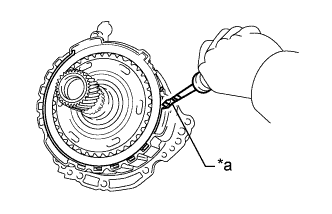
Using a screwdriver with its tip wrapped with protective tape, install the snap ring to the transaxle case sub-assembly as shown in the illustration.
Note
-
Confirm that the snap ring is correctly located in the groove of the transaxle case sub-assembly.
-
Be sure to orient the snap ring so that the edges do not protrude into a cutout on the No. 3 brake piston return spring sub-assembly as shown in the illustration.
-
-
-
INSTALL COUNTER DRIVE GEAR
-
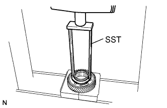
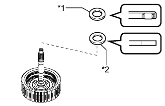
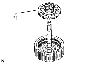
Using SST and a press, install a new counter drive gear bearing inner race (front side) to the counter drive gear.
- SST
- 09387-00020
Note
Make sure to install the counter drive gear bearing inner race (front side) so that there is no clearance between the counter drive gear bearing inner race (front side) and counter drive gear.
-
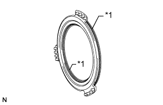
Install 2 new counter drive gear bearings (balls and cage) to the counter drive gear bearing (outer race).
-
Using SST, install the counter drive gear with counter drive gear bearing inner race (front side) and a new counter drive gear bearing inner race (rear side) to the transaxle case sub-assembly.
- SST
- 09223-15030
- 09527-17011
- 09950-60020 ( 09951-00810 )
- 09950-70010 ( 09951-07100 )
-
-
INSTALL FRONT PLANETARY GEAR ASSEMBLY
-
Using SST and a press, install a new front planetary gear assembly to the transaxle case sub-assembly.
- SST
- 09223-15030
- 09527-17011
- 09951-01100
-
-
INSTALL NO. 2 BRAKE PISTON
-
Text in Illustration *1 O-ring Coat 2 new O-rings with ATF and install them to the No. 2 brake piston.
Note
Ensure that the 2 O-rings are not twisted.
-
Install the No. 2 brake piston to the transaxle case sub-assembly.
Note
Be careful not to damage the 2 O-rings.
-
-
INSTALL 1ST AND REVERSE BRAKE RETURN SPRING SUB-ASSEMBLY
-
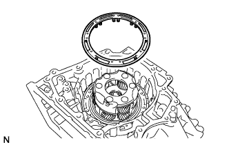
Install the 1st and reverse brake return spring sub-assembly to the transaxle case sub-assembly.
-
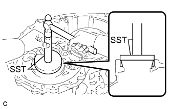
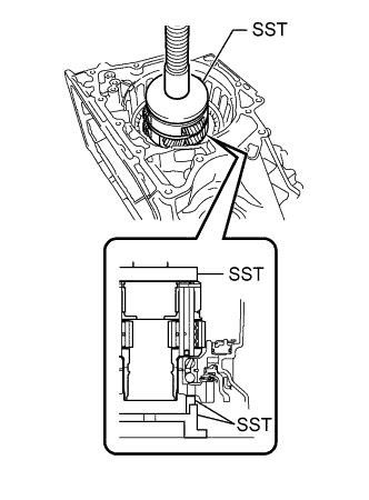
Place SST on the 1st and reverse brake return spring sub-assembly and compress the 1st and reverse brake return spring sub-assembly with a press.
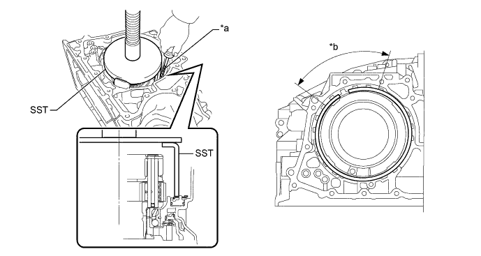
Text in Illustration *a Protective Tape *b Snap Ring End Position - SST
- 09387-00060
Note
Stop the press when the 1st and reverse brake return spring sub-assembly is flush with the snap ring groove. This prevents the 1st and reverse brake return spring sub-assembly from being deformed.
-
Using a screwdriver with its tip wrapped with protective tape, install the snap ring to the transaxle case sub-assembly as shown in the illustration.
Note
-
Confirm that the snap ring is correctly located in the groove of the transaxle case sub-assembly.
-
Be sure to orient the snap ring so that the edges do not protrude into one of the cutouts on the transaxle case sub-assembly as shown in the illustration.
-
Be sure to install the snap ring so that the ends of the snap ring are within the area shown in the illustration.
-
-
-
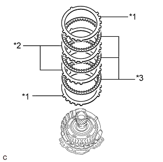
INSTALL NO. 2 BRAKE DISC
-
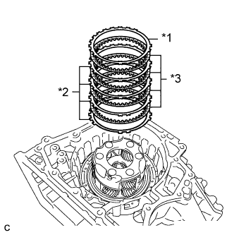
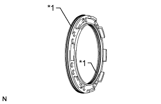
Text in Illustration *1 No. 2 Brake Flange *2 No. 2 Brake Plate *3 No. 2 Brake Disc Install the 4 No. 2 brake discs, 4 No. 2 brake plates and No. 2 brake flange to the transaxle case sub-assembly.
Note
Make sure that the No. 2 brake discs, No. 2 brake plates and No. 2 brake flange are installed in the correct order.
-
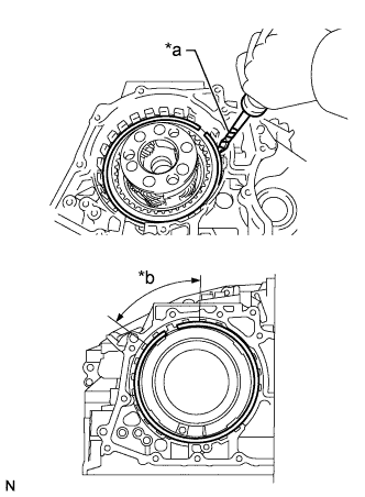
Text in Illustration *a Protective Tape *b Snap Ring End Position Using a screwdriver with its tip wrapped with protective tape, install the snap ring to the transaxle case sub-assembly.
Note
-
Confirm that the snap ring is correctly located in the groove of the transaxle case sub-assembly.
-
Be sure to orient the snap ring so that the edges do not protrude into one of the cutouts on the transaxle case sub-assembly as shown in the illustration.
-
Be sure to install the snap ring so that the ends of the snap ring are within the area shown in the illustration.
-
-
-
INSPECT CLEARANCE OF NO. 2 BRAKE PISTON
-
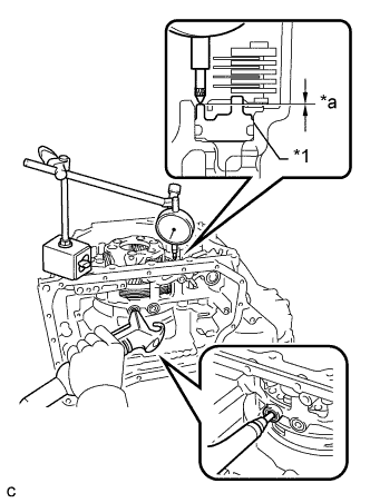
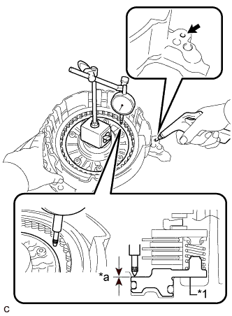
Text in Illustration *1 No. 2 Brake Piston *a Clearance Apply compressed air to the oil hole shown in the illustration, and check the operation of the No. 2 brake piston.
-
Set a dial indicator as shown in the illustration.
-
Using the dial indicator, measure the clearance of the No. 2 brake piston while applying compressed air (350 kPa 3.6 kgf/cm2, 51 psi).
Standard Clearance 0.966 to 1.234 mm (0.0380 to 0.0486 in.) Tech Tips
Measure the clearance at 3 points where the No. 2 brake piston diameter is approximately 140 mm (5.51 in.) and calculate the average.
If the clearance is not as specified, select an appropriate No. 2 brake flange so that the clearance will be within the specified range.
Tech Tips
There are 5 No. 2 brake flanges of different thicknesses.
No. 2 Brake Flange Thickness Part No. Mark Thickness
(mm (in.))
35678-33140 40A 4.0 (0.157) 35678-33150 41A 4.1 (0.161) 35678-33160 42A 4.2 (0.165) 35678-33170 43A 4.3 (0.169) 35678-33180 44A 4.4 (0.173)
-
-
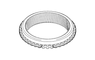
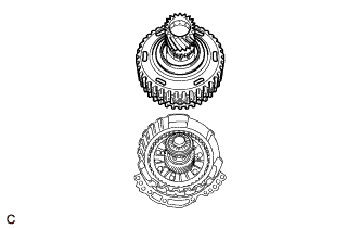
INSTALL PLANETARY RING GEAR FLANGE
-
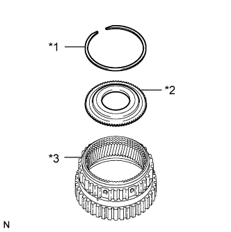
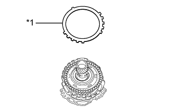
Text in Illustration *1 Snap Ring *2 Planetary Ring Gear Flange *3 Planetary Ring Gear Install the planetary ring gear flange to the planetary ring gear.
-
Using a screwdriver with its tip wrapped with protective tape, install the snap ring to the planetary ring gear.
Note
Confirm that the snap ring is correctly located in the groove of the planetary ring gear.
-
-
INSTALL ONE-WAY CLUTCH ASSEMBLY
-
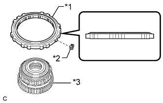
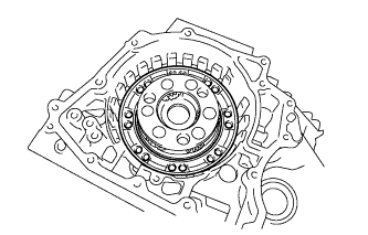
Text in Illustration *1 One-way Clutch Assembly *2 Outer Race Retainer *3 Planetary Ring Gear Install the outer race retainer to the one-way clutch assembly.
-
Install the one-way clutch assembly to the planetary ring gear.
Note
Make sure that the one-way clutch assembly is installed in the correct direction as shown in the illustration.
-
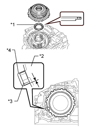
Text in Illustration *1 Thrust Needle Roller Bearing *2 One-way Clutch Assembly *3 Outer Race Retainer *4 Transaxle Case Sub-assembly Coat the thrust needle roller bearing with ATF and install it to the front planetary gear assembly.
Thrust Needle Roller Bearing Diameter - Inside
(mm (in.))
Outside
(mm (in.))
Thrust needle roller bearing 56.1 (2.21) 81.1 (3.19) Note
Be sure to install the thrust needle roller bearing so that the temper colored side of the race is visible.
-
Install the one-way clutch assembly with planetary ring gear to the transaxle case sub-assembly.
Note
-
Make sure that there is no clearance between the outer race retainer and claw on the one-way clutch assembly. If there is any clearance, the spring of the outer race retainer will be deformed.
-
Ensure that there is no clearance between the one-way clutch assembly and transaxle case sub-assembly.
-
-
Text in Illustration *a Protective Tape Using a screwdriver with its tip wrapped with protective tape, install the snap ring to the transaxle case sub-assembly.
Note
-
Confirm that the snap ring is correctly located in the groove of the transaxle case sub-assembly.
-
Be sure to orient the snap ring so that the edges do not protrude into one of the cutouts on the transaxle case sub-assembly as shown in the illustration.
-
-
-
INSTALL PARKING LOCK PAWL
-
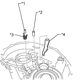
Text in Illustration *1 Parking Lock Pawl Pin *2 Parking Lock Pawl Shaft *3 Spring *4 Parking Lock Pawl Install the parking lock pawl to the transaxle case sub-assembly with the parking lock pawl shaft.
-
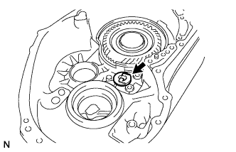
Install the parking lock pawl pin to the transaxle case sub-assembly.
-
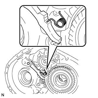
Install the spring to the parking lock pawl pin.
Note
Make sure that one end of the spring is secured in the hole of the transaxle case sub-assembly and the other end is positioned on the parking lock pawl as shown in the illustration.
-
-
INSTALL PARKING LOCK SLEEVE
-
Install the parking lock sleeve to the transaxle case sub-assembly.
-
-
INSTALL PAWL STOPPER PLATE
-
Install the pawl stopper plate to the transaxle case sub-assembly with the 2 bolts.
- Torque:
- 22.7 N*m { 231 kgf*cm, 17 ft.*lbf }
-
-
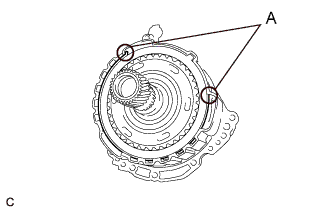
INSTALL NO. 1 TRANSMISSION CASE PLATE
-
Clean and degrease the bolt and installation hole in the transaxle case sub-assembly.
-
Text in Illustration *a Adhesive Apply adhesive to 2 or 3 threads on the end of the bolt.
Adhesive Toyota Genuine Adhesive 1324, Three Bond 1324 or equivalent Note
In order to ensure proper sealing of the bolt, apply adhesive to the bolt and install it within 10 minutes of adhesive application.
-
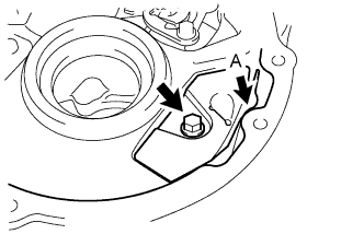
Install the No. 1 transmission case plate to the transaxle case sub-assembly with the bolt.
- Torque:
- 22.7 N*m { 231 kgf*cm, 17 ft.*lbf }
Tech Tips
Tighten the bolt with the part (A) of the No. 1 transmission case plate contacting the transaxle case sub-assembly as shown in the illustration.
-
-
INSTALL PAWL SHAFT CLAMP
-
Install the pawl shaft clamp to the transaxle case sub-assembly with the bolt.
- Torque:
- 22.7 N*m { 231 kgf*cm, 17 ft.*lbf }
-
-
INSTALL COUNTER DRIVEN GEAR
-
Install the counter driven gear to the transaxle case sub-assembly.
-
-
INSTALL COUNTER DRIVE GEAR NUT
-
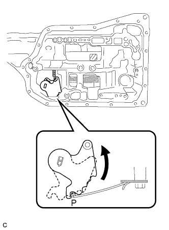
Turn the manual valve lever shaft sub-assembly counterclockwise to set it to the P position as shown in the illustration.
-
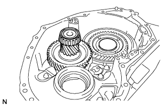
Using SST, install a new counter drive gear nut to the front planetary gear assembly.
- SST
- 09387-00130
- Torque:
- 120 N*m { 1224 kgf*cm, 89 ft.*lbf }
-
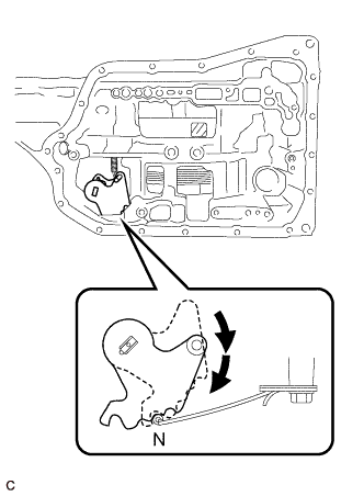
Turn the manual valve lever shaft sub-assembly 2 notches clockwise to set it to the N position as shown in the illustration.
-
Remove the counter driven gear from the transaxle case sub-assembly.
-
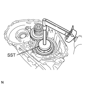
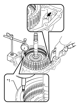
Using SST and a torque wrench, measure the turning torque of the bearing while rotating SST at 60 rpm.
- SST
- 09387-00130
Turning Torque 0.1 to 0.8 N*m (1 to 8 kgf*cm, 1 to 7 in.*lbf) If the measured value is not within the specified range, gradually tighten the nut until the turning torque falls within the specified range.
Maximum Torque 180 N*m (1835 kgf*cm, 133 ft.*lbf) -
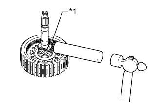
Using SST and a hammer, stake the front planetary gear assembly.
- SST
- 09930-00010
-
Install the counter driven gear to the transaxle case sub-assembly.
-
-
INSTALL FRONT DIFFERENTIAL CASE
-
Install the front differential case to the transaxle case sub-assembly.
-
-
INSTALL NO. 1 BRAKE PISTON
-
Text in Illustration *1 O-ring Coat 2 new O-rings with ATF and install them to the No. 1 brake piston.
Note
Ensure that the 2 O-rings are not twisted.
-
Install the No. 1 brake piston to the front oil pump assembly.
Note
Be careful not to damage the 2 O-rings.
-
-
INSTALL 2ND BRAKE PISTON RETURN SPRING SUB-ASSEMBLY
-
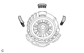
Install the 3 2nd brake piston return spring sub-assemblies to the front oil pump assembly.
Note
Make sure that the 3 2nd brake piston return spring sub-assemblies are installed to the protrusions on the front oil pump assembly.
-
-
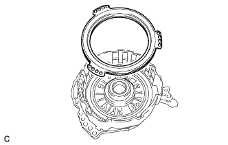
INSTALL NO. 1 BRAKE DISC
-
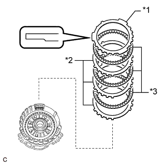
Text in Illustration *1 No. 1 Brake Flange *2 No. 1 Brake Plate *3 No. 1 Brake Disc Install the 3 No. 1 brake discs, 3 No. 1 brake plates and No. 1 brake flange to the front oil pump assembly.
Note
-
Make sure that the No. 1 brake discs, No. 1 brake plates and No. 1 brake flange are installed in the correct order.
-
Be sure to install the No. 1 brake flange in the correct direction.
-
-
Place SST on the No. 1 brake flange and compress the No. 1 brake flange with a press.
- SST
- 09387-00070
- 09495-65040
Note
Stop the press when the 2nd brake piston return spring sub-assemblies are flush with the snap ring groove. This prevents the 2nd brake piston return spring sub-assemblies from being deformed.
-
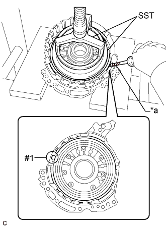
Text in Illustration *a Protective Tape Using a screwdriver with its tip wrapped with protective tape, install the snap ring to the front oil pump assembly as shown in the illustration.
Note
-
Confirm that the snap ring is correctly located in the groove of the front oil pump assembly.
-
Make sure to align the protruding part of the snap ring with the cutout (#1) of the front oil pump assembly shown in the illustration to install the snap ring.
-
-
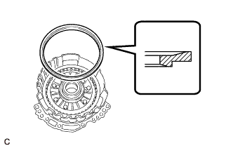
Install the brake snap ring stopper to the front oil pump assembly.
Note
Be sure to install the brake snap ring stopper in the correct direction.
-
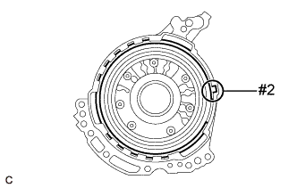
Using a screwdriver with its tip wrapped with protective tape, install the snap ring to the front oil pump assembly as shown in the illustration.
Note
-
Confirm that the snap ring is correctly located in the groove of the front oil pump assembly.
-
Make sure to align the protruding part of the snap ring with the cutout (#2) of the front oil pump assembly shown in the illustration to install the snap ring.
-
-
Text in Illustration *1 Brake Snap Ring Stopper *2 Snap Ring *a Correctly installed Check that the brake snap ring stopper can be turned by hand.
Note
If the brake snap ring stopper cannot be turned by hand, the brake snap ring stopper may have been installed upside down, or a snap ring may not have been completely located in the groove on the front oil pump assembly. Remove and reinstall the snap ring and brake snap ring stopper.
-
-
INSPECT CLEARANCE OF NO. 1 BRAKE PISTON
-
Text in Illustration *1 No. 1 Brake Piston *a Clearance Apply compressed air to the oil hole shown in the illustration, and check the operation of the No. 1 brake piston.
-
Set a dial indicator as shown in the illustration.
-
Using the dial indicator, measure the clearance of the No. 1 brake piston while applying compressed air (350 kPa 3.6 kgf/cm2, 51 psi).
Standard Clearance 0.729 to 0.951 mm (0.0287 to 0.0374 in.) Tech Tips
Measure the clearance at 3 points where the No. 1 brake piston diameter is approximately 140 mm (5.51 in.) and calculate the average.
If the clearance is not as specified, select an appropriate No. 1 brake flange so that the clearance will be within the specified range.
Tech Tips
There are 6 No. 1 brake flanges of different thicknesses.
No. 1 Brake Flange Thickness Part No. Mark Thickness
(mm (in.))
35676-73010 30 3.0 (0.118) 35676-73020 31 3.1 (0.122) 35676-73030 32 3.2 (0.126) 35676-73040 33 3.3 (0.130) 35676-73050 34 3.4 (0.134) 35676-73060 35 3.5 (0.138)
-
-
INSTALL UNDERDRIVE PLANETARY SUN GEAR
-
Text in Illustration *1 Underdrive Planetary Sun Gear *2 Thrust Needle Roller Bearing Coat the thrust needle roller bearing with ATF and install it to the front oil pump assembly.
Thrust Needle Roller Bearing Diameter - Inside
(mm (in.))
Outside
(mm (in.))
Thrust needle roller bearing 57.7 (2.27) 75.2 (2.96) Note
Be sure to install the thrust needle roller bearing so that the temper colored side of the race is visible.
-
Install the underdrive planetary sun gear to the front oil pump assembly.
-
-
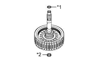
INSTALL INPUT SHAFT SUB-ASSEMBLY
-
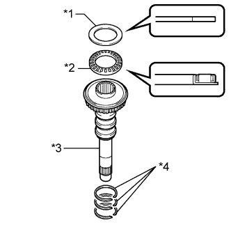
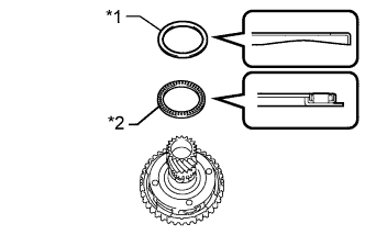
Text in Illustration *1 Thrust Bearing Race *2 Thrust Needle Roller Bearing *3 Input Shaft Sub-assembly *4 Oil Seal Ring Coat 3 new oil seal rings with ATF and install them to the input shaft sub-assembly.
Note
Do not expand the gap of the oil seal ring excessively.
-
Coat the thrust needle roller bearing and thrust bearing race with ATF and install them to the input shaft sub-assembly.
Thrust Needle Roller Bearing and Thrust Bearing Race Diameter - Inside
(mm (in.))
Outside
(mm (in.))
Thrust needle roller bearing 29.1 (1.15) 48.6 (1.91) Thrust bearing race 30.7 (1.21) 48.3 (1.90) Note
Be sure to install the thrust needle roller bearing in the correct direction.
-
Install the input shaft sub-assembly to the front oil pump assembly.
-
-
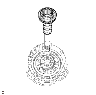
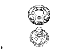
INSTALL PLANETARY SUN GEAR SUB-ASSEMBLY
-
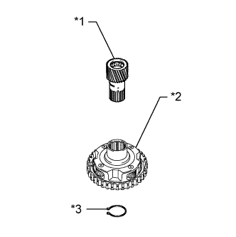
Text in Illustration *1 Planetary Sun Gear Sub-assembly *2 Underdrive Planetary Gear Assembly *3 Snap Ring Using a snap ring expander, install the snap ring to the underdrive planetary gear assembly.
-
Using a snap ring expander, install the planetary sun gear sub-assembly to the underdrive planetary gear assembly with the snap ring expanded.
-
-
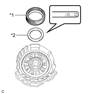
INSTALL UNDERDRIVE PLANETARY RING GEAR
Tech Tips
Perform this procedure only when replacement of the underdrive planetary ring gear or No. 3 brake hub is necessary.
-
Install the snap ring to the underdrive planetary ring gear.
-
Text in Illustration *a Protective Tape While compressing the snap ring with a screwdriver with its tip wrapped with protective tape, install the underdrive planetary ring gear to the No. 3 brake hub.
Note
Confirm that the snap ring is correctly located in the groove of the No. 3 brake hub.
-
-
INSTALL NO. 3 BRAKE HUB
-
Text in Illustration *1 Thrust Bearing Race *2 Thrust Needle Roller Bearing Coat the thrust needle roller bearing and thrust bearing race with ATF and install them to the underdrive planetary gear assembly.
Thrust Needle Roller Bearing and Thrust Bearing Race Diameter - Inside
(mm (in.))
Outside
(mm (in.))
Thrust needle roller bearing 62.6 (2.46) 82.4 (3.24) Thrust bearing race 65.9 (2.59) 82.3 (3.24) Note
Be sure to install the thrust needle roller bearing so that the temper colored side of the race is visible.
-
Install the No. 3 brake hub to the underdrive planetary gear assembly.
-
-
INSTALL UNDERDRIVE PLANETARY GEAR ASSEMBLY
-
Install the underdrive planetary gear assembly to the front oil pump assembly.
-
-
INSTALL NO. 3 BRAKE DISC
-
Text in Illustration *1 No. 3 Brake Flange *2 No. 3 Brake Plate *3 No. 3 Brake Disc Install the 2 No. 3 brake flanges, 3 No. 3 brake discs and 2 No. 3 brake plates to the front oil pump assembly.
Note
Make sure that the No. 3 brake discs, No. 3 brake plates and No. 3 brake flanges are installed in the correct order.
-
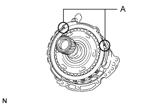
Using a screwdriver with its tip wrapped with protective tape, install the snap ring to the front oil pump assembly.
Note
-
Confirm that the snap ring is correctly located in the groove of the front oil pump assembly.
-
Make sure that the snap ring ends are positioned as shown in the illustration (A).
-
-
-
INSPECT CLEARANCE OF NO. 3 BRAKE PISTON
-
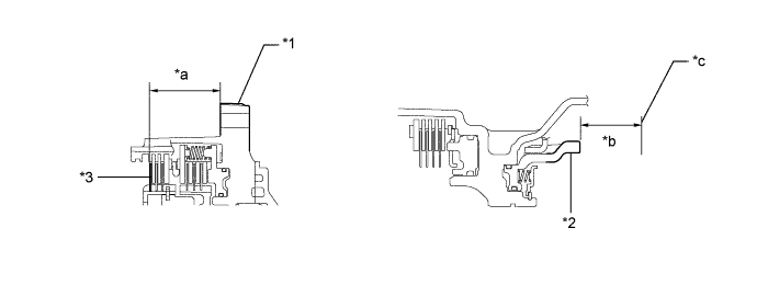
Using a vernier caliper and a straightedge, measure the distance shown in the illustration (Dimension (A)) while a load of 500 N (51 kgf, 112.4 lbf) is being applied to the No. 3 brake flange.
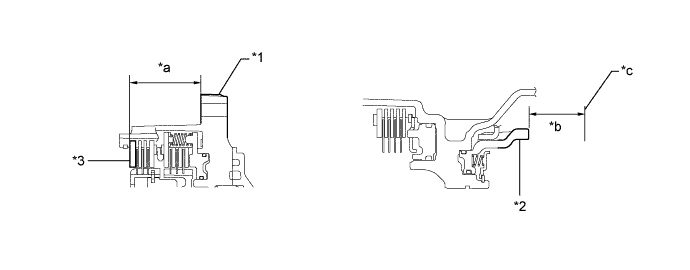
Text in Illustration *1 Front Oil Pump Assembly *2 No. 3 Brake Piston *3 No. 3 Brake Flange - - *a Dimension (A) *b Dimension (B) *c Contact Surface of Front Oil Pump Assembly - - Tech Tips
Measure the distance (Dimension(A)) at 3 points where the No. 3 brake flange diameter is approximately 166 mm (6.54 in.) and calculate the average.
-
Using a vernier caliper and a straightedge, measure the distance shown in the illustration (Dimension (B)).
Tech Tips
Measure the distance (Dimension(B)) at 3 points where the No. 3 brake piston diameter is approximately 166 mm (6.54 in.) and calculate the average.
-
Calculate the clearance using the following formula:
Clearance = Dimension (B) - Dimension (A)
Standard Clearance 0.727 to 0.927 mm (0.0286 to 0.0365 in.) If the clearance is not as specified, select an appropriate No. 3 brake flange so that the clearance will be within the specified range.
-
Adjust clearance of No. 3 brake piston:
-
Text in Illustration *a Protective Tape Using a screwdriver with its tip wrapped with protective tape, remove the snap ring from the front oil pump assembly.
-
Text in Illustration *1 No. 3 Brake Flange Remove the No. 3 brake flange from the front oil pump assembly.
-
Using a vernier caliper and a straightedge, measure the distance shown in the illustration (Dimension (A)) while a load of 500 N (51 kgf, 112.4 lbf) is being applied to the No. 3 brake disc.
Text in Illustration *1 Front Oil Pump Assembly *2 No. 3 Brake Piston *3 No. 3 Brake Disc - - *a Dimension (A) *b Dimension (B) *c Contact Surface of Front Oil Pump Assembly - - Tech Tips
Measure the distance (Dimension(A)) at 3 points where the No. 3 brake disc diameter is approximately 166 mm (6.54 in.) and calculate the average.
-
Using a vernier caliper and a straightedge, measure the distance shown in the illustration (Dimension (B)).
Tech Tips
Measure the distance (Dimension(B)) at 3 points where the No. 3 brake piston diameter is approximately 166 mm (6.54 in.) and calculate the average.
-
Calculate the thickness of the replacement No. 3 brake flange using the following formula:
Thickness of Replacement No. 3 Brake Flange Dimension (B) - Dimension (A) - (0.727 to 0.927 mm (0.0286 to 0.0365 in.)) Tech Tips
There are 6 No. 3 brake flanges of different thicknesses.
No. 3 Brake Flange Thickness Part No. Mark Thickness
(mm (in.))
35679-73020 38 3.8 (0.150) 35679-73030 39 3.9 (0.154) 35679-73040 40 4.0 (0.157) 35679-73050 41 4.1 (0.161) 35679-73060 42 4.2 (0.165) 35679-73070 43 4.3 (0.169) 35679-73080 44 4.4 (0.173) -
Text in Illustration *1 No. 3 Brake Flange Install the No. 3 brake flange to the front oil pump assembly.
-
Using a screwdriver with its tip wrapped with protective tape, install the snap ring to the front oil pump assembly.
Note
-
Confirm that the snap ring is correctly located in the groove of the front oil pump assembly.
-
Make sure that the snap ring ends are positioned as shown in the illustration (A).
-
-
-
-
INSTALL FRONT OIL PUMP ASSEMBLY
-
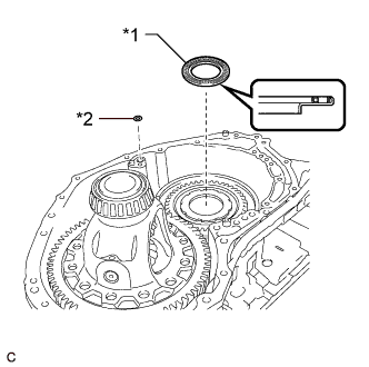
Text in Illustration *1 Thrust Needle Roller Bearing *2 O-ring Coat a new O-ring with ATF and install it to the transaxle case sub-assembly.
-
Coat the thrust needle roller bearing with ATF.
-
Install the thrust needle roller bearing to the counter drive gear nut.
Thrust Needle Roller Bearing Diameter - Inside
(mm (in.))
Outside
(mm (in.))
Thrust needle roller bearing 53.46 (2.10) 79 (3.11) Note
Be sure to install the thrust needle roller bearing so that the temper colored side of the race is visible.
-
Coat the thrust bearing race with MP grease.
-
Text in Illustration *1 Thrust Bearing Race Install the thrust bearing race to the underdrive planetary gear assembly.
Thrust Bearing Race Diameter - Inside
(mm (in.))
Outside
(mm (in.))
Thrust bearing race 59.4 (2.34) 76 (2.99) -
Coat a new front oil pump body O-ring with ATF and install it to the front oil pump body sub-assembly.
Note
Make sure that the front oil pump body O-ring is installed correctly with the identification line facing outward and check that it is not twisted, protruding or damaged.
-
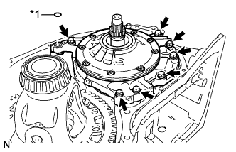
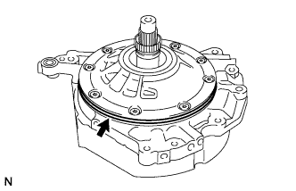
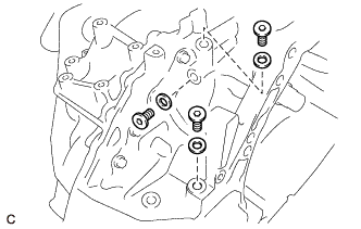
Text in Illustration *1 Gasket Install the front oil pump assembly to the transaxle case sub-assembly with the 7 bolts.
- Torque:
- 22.7 N*m { 231 kgf*cm, 17 ft.*lbf }
-
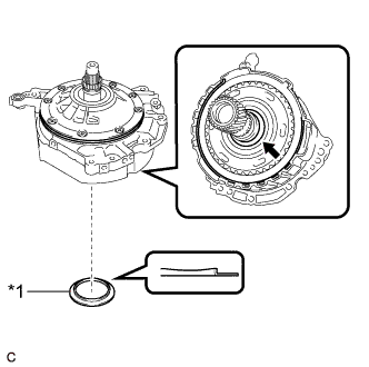
Coat a new gasket with ATF and install it to the front oil pump assembly.
-
-
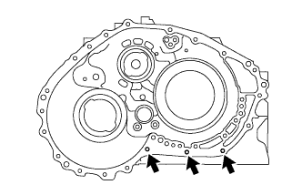
INSTALL TRANSAXLE HOUSING OIL SEPARATOR
-
Clean and degrease the 3 bolts and installation holes in the transaxle housing.
-
Text in Illustration *a Adhesive Apply adhesive to 2 or 3 threads on the ends of the 3 bolts.
Adhesive Toyota Genuine Adhesive 1324, Three Bond 1324 or equivalent Note
In order to ensure proper sealing of the 3 bolts, apply adhesive to the 3 bolts and install them within 10 minutes of adhesive application.
-
Install the transaxle housing oil separator to the transaxle housing with the 3 bolts.
- Torque:
- 22.7 N*m { 231 kgf*cm, 17 ft.*lbf }
-
-
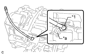
INSTALL DIFFERENTIAL GEAR LUBE APPLY TUBE
-
Clean and degrease the bolt and installation hole in the transaxle housing.
-
Text in Illustration *a Adhesive Apply adhesive to 2 or 3 threads on the end of the bolt.
Adhesive Toyota Genuine Adhesive 1324, Three Bond 1324 or equivalent Note
In order to ensure proper sealing of the bolt, apply adhesive to the bolt and install it within 10 minutes of adhesive application.
-
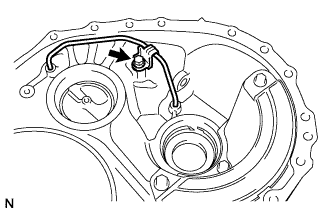
Install the differential gear lube apply tube to the transaxle housing.
Note
Insert the differential gear lube apply tube into the transaxle housing until it makes contact with the stopper.
-
Install the clamp to the transaxle housing with the bolt.
- Torque:
- 22.7 N*m { 231 kgf*cm, 17 ft.*lbf }
Note
There should be clearance between the differential gear lube apply tube and clamp.
-
-
INSTALL TRANSAXLE HOUSING
-
Clean and degrease the 3 bolts and installation holes in the transaxle case sub-assembly.
-
Remove any remaining seal packing from the contact surfaces of the transaxle housing and transaxle case sub-assembly.
Note
Make sure that there is no ATF on the contact surfaces.
-
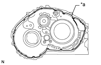
Text in Illustration *a FIPG Apply FIPG to the transaxle case sub-assembly.
FIPG Toyota Genuine Seal Packing 1281, Three Bond 1281 or equivalent Note
-
Apply FIPG in a continuous line (width 1.2 mm (0.0472 in.)) along the sealing surface of the transaxle case sub-assembly.
-
After applying FIPG, install the transaxle housing to the transaxle case sub-assembly within 3 minutes and tighten the bolts within 20 minutes.
-
-
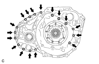
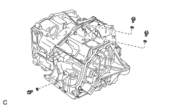
Install the transaxle housing to the transaxle case sub-assembly with the 17 bolts.
- Torque:
- 30.6 N*m { 312 kgf*cm, 23 ft.*lbf }
-
Text in Illustration *a Adhesive Apply adhesive to 2 or 3 threads on the ends of the 3 bolts.
Adhesive Toyota Genuine Adhesive 1324, Three Bond 1324 or equivalent Note
In order to ensure proper sealing of the 3 bolts, apply adhesive to the 3 bolts and install them within 10 minutes of adhesive application.
-
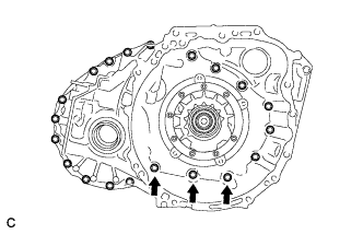
Install the 3 bolts.
- Torque:
- 22.7 N*m { 231 kgf*cm, 17 ft.*lbf }
-
-
INSPECT CLEARANCE OF NO. 1 CLUTCH
-
Install the rear multiple disc clutch assembly to the rear transaxle cover sub-assembly.
-
Check that the piston moves when compressed air (200 kPa, 2.0 kgf/cm2, 29 psi) is applied to the oil hole.
-
Text in Illustration *a Feeler Gauge Using a feeler gauge, measure the No. 1 clutch pack clearance.
Standard Pack Clearance 0.601 to 0.819 mm (0.0237 to 0.0322 in.) Tech Tips
Measure the clearance at 3 points where the flange diameter is approximately 152 mm (5.98 in.) and calculate the average.
If the pack clearance is not as specified, replace the rear multiple disc clutch assembly.
-
-
INSTALL REAR PLANETARY SUN GEAR ASSEMBLY
-
Text in Illustration *1 Thrust Needle Roller Bearing *2 Thrust Bearing Race Coat the thrust needle roller bearing and thrust bearing race with ATF and install them to the rear multiple disc clutch assembly.
Thrust Needle Roller Bearing and Thrust Bearing Race Diameter - Inside
(mm (in.))
Outside
(mm (in.))
Thrust needle roller bearing 28 (1.10) 47.1 (1.85) Thrust bearing race 26.1 (1.03) 44 (1.73) Note
Be sure to install the thrust needle roller bearing so that the temper colored side of the race is visible.
-
Text in Illustration *1 Rear Planetary Sun Gear Assembly Install the rear planetary sun gear assembly to the rear multiple disc clutch assembly.
-
Text in Illustration *1 Snap Ring Using a brass bar and a hammer, install the snap ring to the rear multiple disc clutch assembly.
Tech Tips
Use a piece of cloth to keep the snap ring from flying off.
-
-
INSPECT CLEARANCE OF NO. 2 CLUTCH
-
Install the rear multiple disc clutch assembly to the rear transaxle cover sub-assembly.
-
Text in Illustration *1 No. 2 Direct Clutch Piston Using a dial indicator, measure the No. 2 clutch pack clearance while applying compressed air (200 kPa, 2.0 kgf/cm2, 29 psi).
Standard Pack Clearance 0.394 to 0.605 mm (0.0155 to 0.0238 in.) Tech Tips
Measure the clearance at 3 points where the diameter of the No. 2 direct clutch piston is approximately 152 mm (5.98 in.) and calculate the average.
If the pack clearance is not as specified, replace the rear multiple disc clutch assembly.
-
-
INSTALL REAR MULTIPLE DISC CLUTCH ASSEMBLY
-
Text in Illustration *1 O-ring *2 Oil Seal Ring Coat a new O-ring with ATF and install it to the rear multiple disc clutch assembly.
Note
Ensure that the O-ring is not twisted.
-
Coat a new oil seal ring with ATF and install it to the rear multiple disc clutch assembly.
-
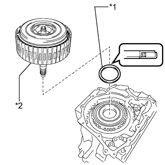
Text in Illustration *1 Thrust Needle Roller Bearing *2 Rear Multiple Disc Clutch Assembly Coat the thrust needle roller bearing with ATF and install it to the transaxle case sub-assembly.
Thrust Needle Roller Bearing Diameter - Inside
(mm (in.))
Outside
(mm (in.))
Thrust needle roller bearing 61.2 (2.41) 79 (3.11) -
Install the rear multiple disc clutch assembly to the transaxle case sub-assembly.
-
-
INSPECT INTERMEDIATE SHAFT END PLAY
-
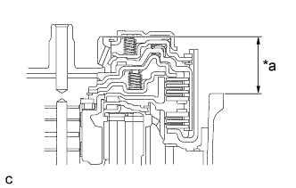
Text in Illustration *a Dimension (A) Clean the contact surfaces of the transaxle case sub-assembly and rear transaxle cover sub-assembly.
-
Place a straightedge on the multiple direct clutch drum and measure the distance between the transaxle case sub-assembly and the straightedge (Dimension (A)) using a vernier caliper.
-
Text in Illustration *a Dimension (B) Using a vernier caliper and a straightedge, measure the distance shown in the illustration (Dimension (B)).
-
Calculate the end play using the following formula:
End play = Dimension (B) - Dimension (A) - Thrust needle roller bearing thickness
Standard End Play 0.022 to 1.099 mm (0.000866 to 0.0433 in.)
-
-
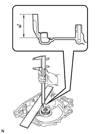
INSTALL REAR TRANSAXLE COVER SUB-ASSEMBLY
-
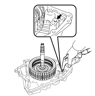
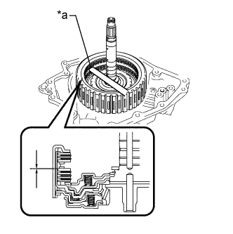
Text in Illustration *a Depth Using SST and a hammer, install a new needle roller bearing to the rear transaxle cover sub-assembly.
- SST
- 09950-60010 ( 09951-00220 )
- 09950-70010 ( 09951-07100 )
Standard Depth 21.5 to 21.9 mm (0.846 to 0.862 in.) -
Clean and degrease the 2 "TORX" screws and installation holes in the rear transaxle cover sub-assembly.
-
Text in Illustration *a Adhesive Apply adhesive to 2 or 3 threads on the ends of the 2 "TORX" screws.
Adhesive Toyota Genuine Adhesive 1324, Three Bond 1324 or equivalent Note
In order to ensure proper sealing of the 2 "TORX" screws, apply adhesive to the 2 "TORX" screws and install them within 10 minutes of adhesive application.
-
Using a T30 "TORX" socket wrench, install the rear transaxle cover plate to the rear transaxle cover sub-assembly with the 2 "TORX" screws.
- Torque:
- 7.5 N*m { 76 kgf*cm, 66 in.*lbf }
-
Text in Illustration *1 Oil Seal Ring Coat 2 new oil seal rings with ATF and install them to the rear transaxle cover sub-assembly.
Note
Confirm that the 2 oil seal rings are correctly located in the grooves of the rear transaxle cover sub-assembly.
-
Text in Illustration *1 Thrust Needle Roller Bearing *2 Thrust Bearing Race Coat the thrust needle roller bearing and thrust bearing race with MP grease and install them to the rear transaxle cover sub-assembly.
Thrust Needle Roller Bearing and Thrust Bearing Race Diameter - Inside
(mm (in.))
Outside
(mm (in.))
Thrust needle roller bearing 48.9 (1.93) 72.0 (2.83) Thrust bearing race 52.2 (2.06) 70.4 (2.77) -

Coat 3 new O-rings with ATF and install them to the transaxle case sub-assembly.
-
Clean and degrease the 2 bolts and installation holes in the transaxle case sub-assembly.
-
Remove any remaining seal packing from the contact surfaces of the rear transaxle cover sub-assembly and transaxle case sub-assembly.
Note
Make sure that there is no ATF on the contact surfaces.
-

Text in Illustration *a FIPG Apply FIPG to the transaxle case sub-assembly.
FIPG Toyota Genuine Seal Packing 1281, Three Bond 1281 or equivalent Note
-
Apply FIPG in a continuous line (width 1.2 mm (0.0472 in.)) along the sealing surface of the transaxle case sub-assembly.
-
After applying FIPG, install the rear transaxle cover sub-assembly to the transaxle case sub-assembly within 3 minutes and tighten the bolts within 20 minutes.
-
-
Install the rear transaxle cover sub-assembly to the transaxle case sub-assembly with the 12 bolts.
- Torque:
- 22.7 N*m { 231 kgf*cm, 17 ft.*lbf }
-
Text in Illustration *a Adhesive Apply adhesive to 2 or 3 threads on the ends of the 2 bolts.
Adhesive Toyota Genuine Adhesive 1324, Three Bond 1324 or equivalent Note
In order to ensure proper sealing of the 2 bolts, apply adhesive to the 2 bolts and install them within 10 minutes of adhesive application.
-
Install the 2 bolts.
- Torque:
- 16.9 N*m { 172 kgf*cm, 12 ft.*lbf }
-
-
INSTALL REAR TRANSAXLE COVER PLUG
-
Coat 3 new O-rings with ATF and install them to the 3 rear transaxle cover plugs.
Note
Ensure that the 3 O-rings are not twisted.
-
Install the 3 rear transaxle cover plugs to the rear transaxle cover sub-assembly.
- Torque:
- 7.4 N*m { 75 kgf*cm, 65 in.*lbf }
-
-
INSTALL REFILL PLUG
-
Install a new gasket to the refill plug.
-
Install the refill plug to the rear transaxle cover sub-assembly.
- Torque:
- 49 N*m { 500 kgf*cm, 36 ft.*lbf }
-
-
INSPECT INPUT SHAFT SUB-ASSEMBLY END PLAY
-
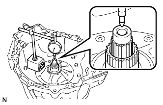
Using a dial indicator, measure the input shaft sub-assembly end play.
Standard End Play 0.020 to 1.242 mm (0.000787 to 0.0489 in.)
-
-
INSTALL TRANSAXLE CASE GASKET
-
Coat 2 new transaxle case gaskets with ATF.
-
Install the 2 transaxle case gaskets to the transaxle case sub-assembly.
-
-
INSTALL TRANSMISSION VALVE BODY ASSEMBLY
-
Coat the O-ring of the transmission wire with ATF.
-
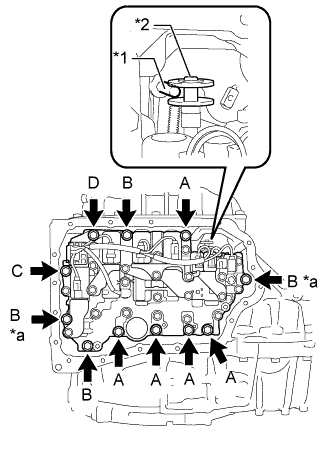
Text in Illustration *1 Manual Valve Lever Shaft Sub-assembly Pin *2 Manual Valve *a Positioning Bolt Insert the manual valve lever shaft sub-assembly pin into the groove on the end of the manual valve as shown in the illustration and temporarily install the transmission valve body assembly to the transaxle case sub-assembly with the 11 bolts.
Bolt Length Bolt Bolt Length
(mm (in.))
(A) 25 (0.984) (B) 30 (1.18) (C) and (D) 35 (1.38) Note
-
When installing the transmission valve body assembly, be careful not to allow the transmission revolution sensor and transaxle case sub-assembly to interfere with each other.
-
Be sure to insert the pin of the manual valve lever shaft sub-assembly pin into the groove on the end of the manual valve.
-
-
Fully tighten the 2 positioning bolts shown in the illustration.
- Torque:
- 10.8 N*m { 110 kgf*cm, 8 ft.*lbf }
-
Fully tighten the 9 bolts to install the transmission valve body assembly.
- Torque:
- Bolt (A), (B), (C)
- 10.8 N*m { 110 kgf*cm, 8 ft.*lbf }
- Bolt (D)
- 9.6 N*m { 98 kgf*cm, 85 in.*lbf }
-
-
INSTALL VALVE BODY OIL STRAINER ASSEMBLY
-
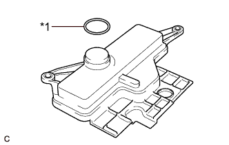
Text in Illustration *1 O-ring Coat a new O-ring with ATF.
-
Install the O-ring to the valve body oil strainer assembly.
Note
Ensure that the O-ring is not twisted.
-
Install the valve body oil strainer assembly to the transmission valve body assembly with the 2 bolts.
- Torque:
- 9.6 N*m { 98 kgf*cm, 85 in.*lbf }
-
-
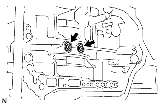
INSTALL TRANSMISSION OIL CLEANER MAGNET
-
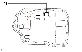
Text in Illustration *1 Transmission Oil Cleaner Magnet Install the 4 transmission oil cleaner magnets to the automatic transaxle oil pan sub-assembly as shown in the illustration.
-
-
INSTALL AUTOMATIC TRANSAXLE OIL PAN GASKET
-
Install a new automatic transaxle oil pan gasket to the automatic transaxle oil pan sub-assembly.
-
-
INSTALL AUTOMATIC TRANSAXLE OIL PAN SUB-ASSEMBLY
-
Clean and degrease the 2 bolts and installation holes in the transaxle case sub-assembly.
-
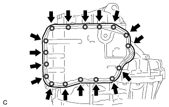
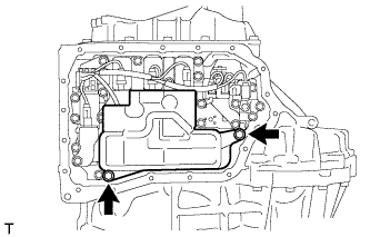
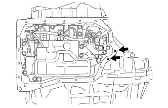
Install the automatic transaxle oil pan sub-assembly with automatic transaxle oil pan gasket to the transaxle case sub-assembly with the 17 bolts.
- Torque:
- 7.5 N*m { 76 kgf*cm, 66 in.*lbf }
Note
Completely remove any oil or grease from the contact surfaces of the transaxle case sub-assembly and automatic transaxle oil pan sub-assembly with automatic transaxle oil pan gasket before installation.
-
Text in Illustration *a Adhesive Apply adhesive to 2 or 3 threads on the ends of the 2 bolts.
Adhesive Toyota Genuine Adhesive 1344, Three Bond 1344 or equivalent Note
In order to ensure proper sealing of the 2 bolts, apply adhesive to the 2 bolts and install them within 10 minutes of adhesive application.
-
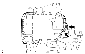
Install the 2 bolts.
- Torque:
- 7.0 N*m { 71 kgf*cm, 62 in.*lbf }
-
-
INSTALL NO. 1 TRANSMISSION OIL FILLER TUBE
-
Using a 6 mm hexagon socket wrench, install the No. 1 transmission oil filler tube to the automatic transaxle oil pan sub-assembly.
- Torque:
- 0.8 N*m { 8 kgf*cm, 7 in.*lbf }
-
-
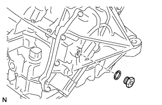
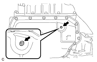
INSTALL OVERFLOW PLUG
-
Using a 6 mm hexagon socket wrench, install the overflow plug and a new gasket to the automatic transaxle oil pan sub-assembly.
- Torque:
- 40 N*m { 408 kgf*cm, 30 ft.*lbf }
-
-
INSTALL FRONT DRIVE SHAFT OIL SEAL LH
-
Coat the lip of a new front drive shaft oil seal LH with MP grease.
-
Text in Illustration *a Depth Using SST and a hammer, install the front drive shaft oil seal LH to the transaxle case sub-assembly.
- SST
- 09316-10010
- 09950-70010 ( 09951-07100 )
Standard Depth -0.5 to 0.5 mm (-0.0197 to 0.0197 in.) Note
-
Make sure that the front drive shaft oil seal LH is installed in the correct direction.
-
Do not damage the lip of the front drive shaft oil seal LH.
-
-
INSTALL FRONT DRIVE SHAFT OIL SEAL RH
-
Coat the lip of a new front drive shaft oil seal RH with MP grease.
-
Text in Illustration *a Depth Using SST and a hammer, install the front drive shaft oil seal RH to the transaxle housing.
- SST
- 09316-60011 ( 09316-00011 )
Standard Depth -0.5 to 0.5 mm (-0.0197 to 0.0197 in.) Note
-
Make sure that the front drive shaft oil seal RH is installed in the correct direction.
-
Do not damage the lip of the front drive shaft oil seal RH.
-
-
INSTALL NO. 2 TRANSAXLE CASE PLUG
-
Clean and degrease the 3 No. 2 transaxle case plugs and installation holes in the transaxle housing.
-
Install 3 new gaskets to the 3 No. 2 transaxle case plugs.
-
Text in Illustration *a Adhesive Apply adhesive to 2 or 3 threads on the ends of the 3 No. 2 transaxle case plugs.
Adhesive Toyota Genuine Adhesive 1324, Three Bond 1324 or equivalent Note
In order to ensure proper sealing of the 3 No. 2 transaxle case plugs, apply adhesive to the 3 No. 2 transaxle case plugs and install them within 10 minutes of adhesive application.
-
Using a 6 mm hexagon socket wrench, install the 3 No. 2 transaxle case plugs to the transaxle housing.
- Torque:
- 17 N*m { 173 kgf*cm, 13 ft.*lbf }
-
-
INSTALL NO. 1 TRANSAXLE CASE PLUG
-
Coat 3 new O-rings with ATF and install them to the 3 No. 1 transaxle case plugs.
Note
Ensure that the 3 O-rings are not twisted.
-
Install the 3 No. 1 transaxle case plugs to the transaxle case sub-assembly.
- Torque:
- 7.4 N*m { 75 kgf*cm, 65 in.*lbf }
-
-
INSTALL OIL COOLER INLET ELBOW
-
Coat a new O-ring with ATF and install it to the oil cooler inlet elbow.
Note
Ensure that the O-ring is not twisted.
-
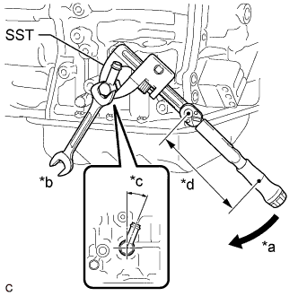
Text in Illustration *a Turn *b Hold *c 20 to 24° *d Torque Wrench Fulcrum Length Using SST, install the oil cooler inlet elbow to the transaxle case sub-assembly so that it is positioned as shown in the illustration.
- SST
- 09922-10010
Torque Specified tightening torque 27 N*m (275 kgf*cm, 20 ft.*lbf) Tech Tips
-
Calculate the torque wrench reading when changing the fulcrum length of the torque wrench. Click here
-
When using SST (fulcrum length of 137 mm (5.39 in.)) + torque wrench (fulcrum length of 180 mm (7.09 in.)): 15.3 N*m (156 kgf*cm, 11 ft.*lbf)
-
-
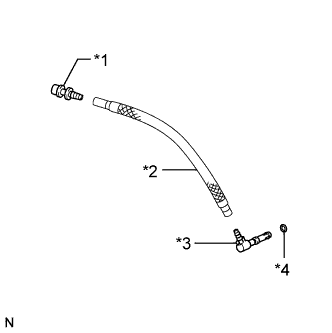
INSTALL OIL COOLER UNION SUB-ASSEMBLY
-
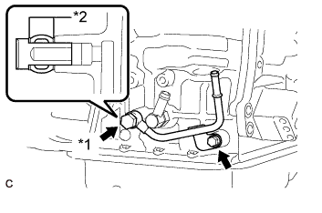
Text in Illustration *1 Union Bolt *2 Gasket Temporarily install the oil cooler union sub-assembly to the transaxle case sub-assembly with the bolt.
-
Install the union bolt and 2 new gaskets to the transaxle case sub-assembly as shown in the illustration.
- Torque:
- 27 N*m { 275 kgf*cm, 20 ft.*lbf }
-
Tighten the bolt.
- Torque:
- 12 N*m { 122 kgf*cm, 9 ft.*lbf }
-
-
INSTALL PARK/NEUTRAL POSITION SWITCH ASSEMBLY
-
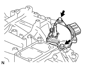
Temporarily install the park/neutral position switch assembly to the transaxle case sub-assembly with the 2 bolts.
Note
Before installing the park/neutral position switch assembly, remove any dirt or rust on the manual valve lever shaft sub-assembly. Be sure to install the park/neutral position switch assembly straight along the manual valve lever shaft sub-assembly while being careful not to deform the plate spring that supports the manual valve lever shaft sub-assembly. If the plate spring is deformed, the park/neutral position switch assembly cannot be reinstalled correctly.
-
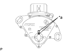
Text in Illustration *a Protrusion Align the protrusions of the park/neutral position switch assembly as shown in the illustration.
-
Tighten the 2 bolts.
- Torque:
- 5.4 N*m { 55 kgf*cm, 48 in.*lbf }
Note
After installing the park/neutral position switch assembly, confirm that the 2 protrusions on the park/neutral position switch assembly are aligned.
-
-
INSTALL TRANSMISSION CONTROL SHAFT LEVER
-
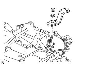
Install the transmission control shaft lever to the manual valve lever shaft sub-assembly with the washer and nut.
- Torque:
- 12.7 N*m { 130 kgf*cm, 9 ft.*lbf }
-
-
INSTALL TRANSMISSION BREATHER HOSE SUB-ASSEMBLY
-
Text in Illustration *1 No. 1 Breather Plug *2 Breather Plug Hose *3 No. 2 Breather Plug *4 O-ring Coat a new O-ring with ATF and install it to the No. 2 breather plug.
Note
Ensure that the O-ring is not twisted.
-
Install the No. 2 breather plug to the breather plug hose.
-
Install the No. 1 breather plug to the breather plug hose.
-
Text in Illustration *1 No. 2 Breather Plug *a Boss Install the transmission breather hose sub-assembly to the transaxle case sub-assembly.
Note
Make sure that the stopper of the No. 2 breather plug is in contact with the side of the boss on the transaxle case sub-assembly.
-