SHIFT LEVER (for TMMK Made) REMOVAL
-
PRECAUTION
CAUTION:
Be sure to read Precaution thoroughly before servicing Click here.
Note
After turning the engine switch off, waiting time may be required before disconnecting the cable from the negative (-) battery terminal. Therefore, make sure to read the disconnecting the cable from the negative (-) battery terminal notices before proceeding with work Click here.
-
REMOVE SHIFT LOCK RELEASE BUTTON COVER
-
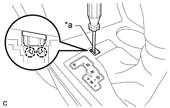
Text in Illustration *a Protective Tape Using a screwdriver, disengage the 2 claws to remove the shift lock release button cover from the shift position indicator.
Note
Be careful not to damage the shift lock release button cover.
Tech Tips
Tape the screwdriver tip before use.
-
-
DISCONNECT CABLE FROM NEGATIVE BATTERY TERMINAL
CAUTION:
Wait at least 90 seconds after disconnecting the cable from the negative (-) battery terminal to disable the SRS system.
Note
When disconnecting the cable, some systems need to be initialized after the cable is reconnected Click here.
-
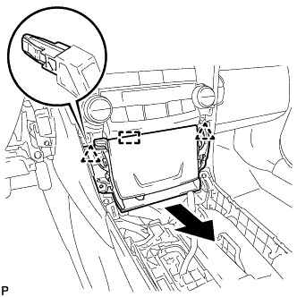
REMOVE REAR CONSOLE BOX ASSEMBLY
-
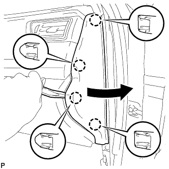
REMOVE FRONT DOOR SCUFF PLATE LH
-
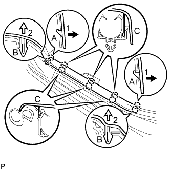
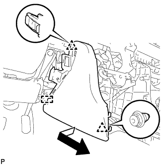
Disengage the 2 claws (A) in the direction indicated by the arrows (1) shown in the illustration.
-
Disengage the 2 claws (B) in the direction indicated by the arrows (2) shown in the illustration.
-
Disengage the 6 claws (C) to remove the front door scuff plate LH.
-
-
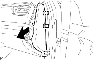
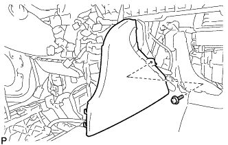
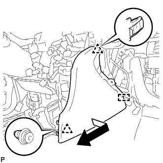
REMOVE COWL SIDE TRIM SUB-ASSEMBLY LH
-
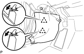
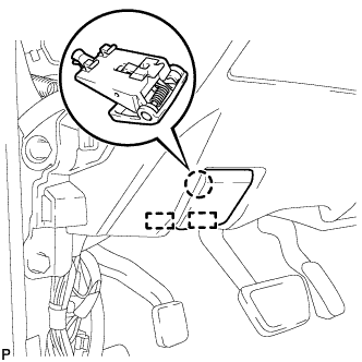
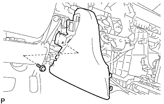
Remove the clip.
-
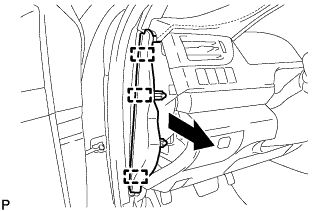
Pull the cowl side trim sub-assembly LH as shown in the illustration to disengage the 2 clips and remove the cowl side trim sub-assembly LH.
-
-
REMOVE FRONT DOOR OPENING TRIM WEATHERSTRIP LH
-
Remove the front door opening trim weatherstrip LH.
-
-
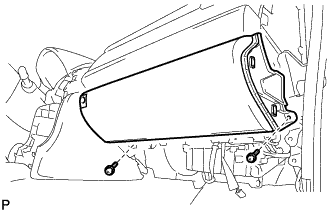
REMOVE INSTRUMENT SIDE PANEL LH
-
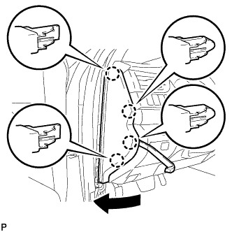
Using a moulding remover, disengage the 4 claws as shown in the illustration.
-
Disengage the 3 guides and remove the instrument side panel LH as shown in the illustration.
-
-
DISCONNECT HOOD LOCK CONTROL LEVER SUB-ASSEMBLY
-
Disengage the claw and 2 guides to disconnect the hood lock control lever sub-assembly.
-
-
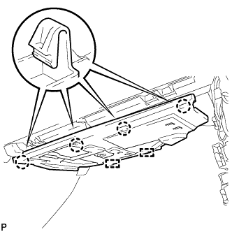
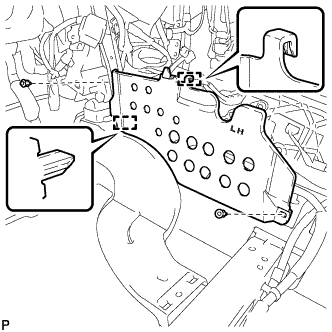
REMOVE LOWER NO. 1 INSTRUMENT PANEL FINISH PANEL ASSEMBLY
-
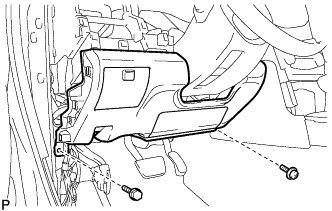
Remove the bolt <B> and screw <C> or <D>.
-
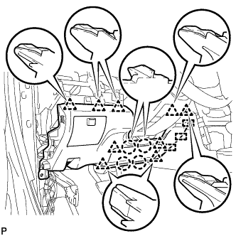
Disengage the 4 claws, 9 clips and 3 guides to remove the lower No. 1 instrument panel finish panel assembly.
-
-
REMOVE FRONT DOOR SCUFF PLATE RH
Tech Tips
Use the same procedure as for the LH side.
-
REMOVE COWL SIDE TRIM SUB-ASSEMBLY RH
Tech Tips
Use the same procedure as for the LH side Click here.
-
REMOVE FRONT DOOR OPENING TRIM WEATHERSTRIP RH
Tech Tips
Use the same procedure as for the LH side.
-
REMOVE INSTRUMENT SIDE PANEL RH
-
Using a moulding remover, disengage the 4 claws as shown in the illustration.
-
Disengage the 3 guides to remove the instrument side panel RH as shown in the illustration.
-
-
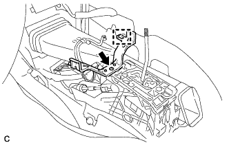
REMOVE NO. 2 INSTRUMENT PANEL UNDER COVER SUB-ASSEMBLY
-
Disengage the 4 claws.
-
Disengage the 2 guides.
-
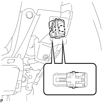
Disconnect the connector to remove the No. 2 instrument panel under cover sub-assembly.
-
-
REMOVE LOWER NO. 2 INSTRUMENT PANEL AIRBAG ASSEMBLY
-
REMOVE LOWER INSTRUMENT PANEL SUB-ASSEMBLY
-
Remove the 2 screws <C> or <D>.
-
Open the lower instrument panel door.
-
Remove the 3 screws <C> or <D>.
-
Disengage the 2 clips and guide as shown in the illustration.
-
Disengage the clamp.
-
Disengage the glove compartment light as shown in the illustration.
-
Disconnect the connector and remove the lower instrument panel sub-assembly.
-
-
REMOVE UPPER CONSOLE PANEL SUB-ASSEMBLY
-
Remove the 2 screws <C> or <D>.
-
Disengage the 2 clips and guide as shown in the illustration.
-
Disconnect each connector to remove the upper console panel sub-assembly.
-
-
REMOVE FRONT NO. 2 CONSOLE BOX INSERT
-
Disengage the 2 claws to disconnect the room temperature sensor from the front No. 2 console box insert.
-
Remove the screw <C> or <D>.
-
Disengage the 2 clips and guide to remove the front No. 2 console box insert as shown in the illustration.
-
-
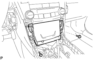
REMOVE CONSOLE BOX INSERT
-
Remove the screw <C> or <D>.
-
Disengage the 2 clips and guide to remove the console box insert as shown in the illustration.
-
-
REMOVE FLOOR CARPET BRACKET LH
-
Remove the 2 clips.
-
Disengage the 2 guides to remove the floor carpet bracket LH.
-
-
REMOVE NO. 1 CONSOLE BOX MOUNTING BRACKET
-
Disengage the guide.
-
Remove the screw and No. 1 console box mounting bracket from the lower shift lever assembly.
-
-
REMOVE NO. 1 CONSOLE BOX DUCT
-
Remove the clip and No. 1 console box duct from the lower shift lever assembly.
-
-
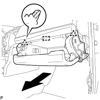
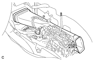
REMOVE LOWER SHIFT LEVER ASSEMBLY
-
Disconnect the end of the transmission control cable assembly from the lower shift lever assembly.
-
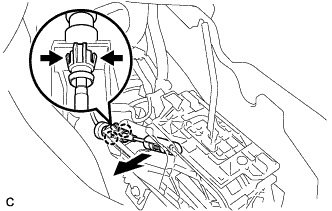
Disengage the 2 claws to disconnect the transmission control cable assembly from the lower shift lever assembly.
-
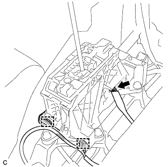
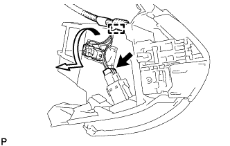
Disconnect the shift lock control ECU connector.
-
Disengage the 2 clamps.
-
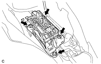
Remove the 4 bolts and lower shift lever assembly from the shift lever support.
-
-
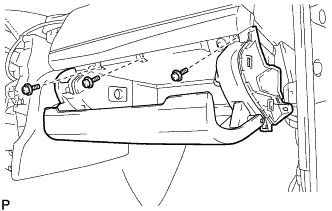
REMOVE SHIFT LEVER SUPPORT
-
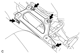
Remove the 4 bolts and shift lever support from the vehicle body.
-