ENGINE SWITCH REMOVAL
-
PRECAUTION
Note
After turning the engine switch off, waiting time may be required before disconnecting the cable from the negative (-) battery terminal. Therefore, make sure to read the disconnecting the cable from the negative (-) battery terminal notices before proceeding with work Click here.
-
DISCONNECT CABLE FROM NEGATIVE BATTERY TERMINAL
Note
When disconnecting the cable, some systems need to be initialized after the cable is reconnected Click here.
-
REMOVE RADIO RECEIVER ASSEMBLY WITH AIR CONDITIONING CONTROL ASSEMBLY (w/o Navigation System)
-
REMOVE NAVIGATION RECEIVER ASSEMBLY WITH AIR CONDITIONING CONTROL ASSEMBLY (w/ Navigation System)
-
REMOVE FRONT DOOR SCUFF PLATE LH
-
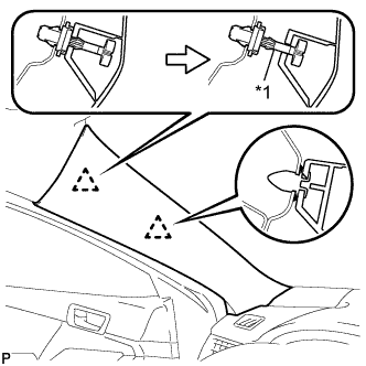
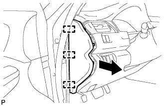
Text in Illustration *1 Front Pillar Garnish Clip Pull the upper part of the garnish toward the inside of the cabin and disengage the garnish from the base of the 2 clips.
Tech Tips
Make the front pillar garnish LH hang down from the front pillar garnish clip.
-
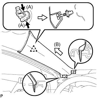
While pushing the tabs on the front pillar garnish clip in the direction indicated by the arrow (A) shown in the illustration, disengage the front pillar garnish clip.
-
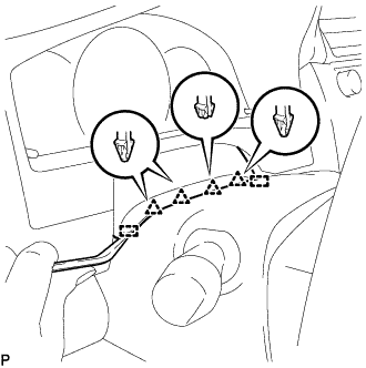
Pull the garnish in the direction indicated by the arrow (B) shown in the illustration to disengage the 2 guides and remove the front pillar garnish LH.
-

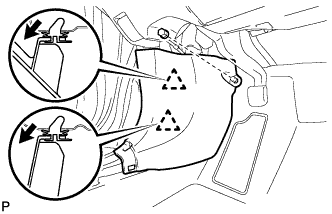
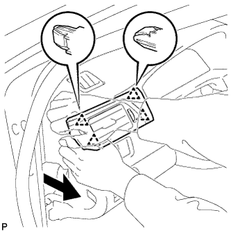
Text in Illustration *1 Adhesive Tape *2 Protective Cover *3 Curtain Shield Airbag Assembly Protect the curtain shield airbag assembly.
-
Cover the airbag with a piece of cloth or nylon and secure the edges of the cover with tape as shown in the illustration.
Note
Cover the curtain shield airbag with a protective cover as soon as the front pillar garnish is removed.
-
-
-
REMOVE COWL SIDE TRIM SUB-ASSEMBLY LH
-
Remove the clip.
-
Disengage the 2 clips and remove the cowl side trim sub-assembly LH.
-
-
DISCONNECT FRONT DOOR OPENING TRIM WEATHERSTRIP LH
-

Disconnect the front door opening trim weatherstrip LH.
-
-
REMOVE INSTRUMENT SIDE PANEL LH
-
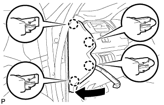
Using a moulding remover, disengage the 4 claws as shown in the illustration.
-
Disengage the 3 guides and remove the instrument side panel LH as shown in the illustration.
-
-
REMOVE NO. 1 INSTRUMENT PANEL REGISTER ASSEMBLY
-
Disengage the 4 clips to remove the No. 1 instrument panel register assembly as shown in the illustration.
-
-
REMOVE INSTRUMENT CLUSTER FINISH PANEL ASSEMBLY
-
for Manual Tilt and Manual Telescopic Steering Column:
-
Operate the tilt and telescopic lever to fully extend and lower the steering column assembly.
-
-
Using a moulding remover, disengage the 4 clips and 2 guides.
-
for LHD:
-
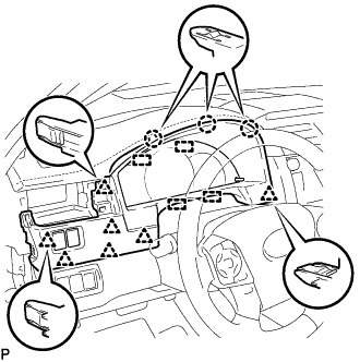
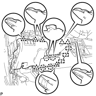
Disengage the 3 claws, 7 clips and 4 guides.
-
-
for RHD:
-
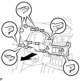
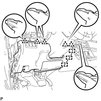
Disengage the 4 claws, 5 clips and 4 guides as shown in the illustration.
-
-
Disconnect each connector.
-
Remove the instrument cluster finish panel assembly as shown in the illustration.
-
-
DISCONNECT HOOD LOCK CONTROL LEVER SUB-ASSEMBLY
-
Disengage the claw and 2 guides to disconnect the hood lock control lever sub-assembly.
-
-
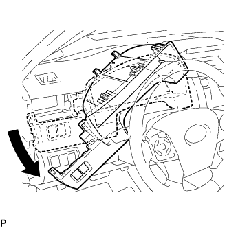
REMOVE INSTRUMENT PANEL SUB-ASSEMBLY
-
Remove the 2 bolts <B>.
-
w/o Driver Side Knee Airbag:
-
Disengage the 5 clips and 3 guides to remove the instrument panel sub-assembly.
-
-
w/ Driver Side Knee Airbag:
-
Disengage the 4 claws, 7 clips and 3 guides to remove the instrument panel sub-assembly.
-
-
-
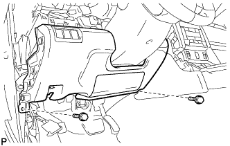
REMOVE FRONT ASH RECEPTACLE ASSEMBLY
-
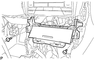
Remove the 2 screws <D>.
-
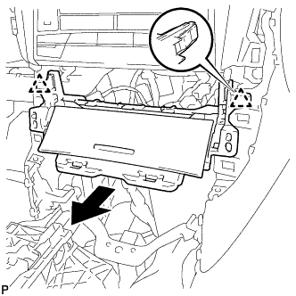
Disengage the 2 clips as shown in the illustration.
-
Disconnect each connector to remove the front ash receptacle assembly.
-
-
REMOVE CONSOLE BOX ASSEMBLY
-
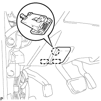
REMOVE FRONT NO. 2 CONSOLE BOX INSERT
-
for LHD:
-
Disengage the 2 claws to disconnect the room temperature sensor from the front No. 2 console box insert.
-
-
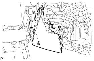
Remove the 2 screws <D>.
-
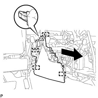
Disengage the clip and 4 guides to remove the front No. 2 console box insert as shown in the illustration.
-
-
REMOVE LOWER INSTRUMENT PANEL FINISH PANEL ASSEMBLY
-
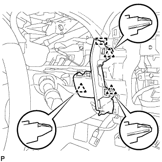
Disengage the 3 clips and guide to remove the lower instrument panel finish panel assembly.
-
for LHD with Smart Entry and Start System:
-
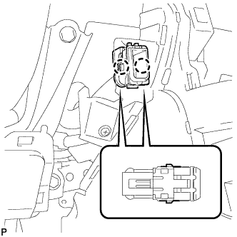
Disconnect the connector.
-
-
-
REMOVE ENGINE SWITCH
-
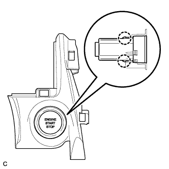
Disengage the 2 claws and remove the engine switch.
-