POWER WINDOW CONTROL SYSTEM(for Models with Jam Protection Function on Driver Door Window Only) Front Passenger Side Power Window does not Operate with Front Passenger Side Power Window Switch
DESCRIPTION
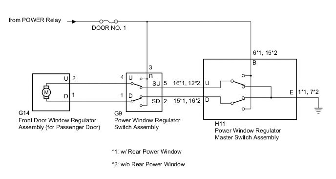
When the ignition switch is ON, the front door window regulator assembly (for passenger door) is operated by the power window regulator switch assembly.
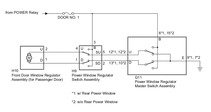
WIRING DIAGRAM
-
for LHD
-
for RHD
CAUTION / NOTICE / HINT
Note
-
Inspect the fuses for circuits related to this system before performing the following procedure.
-
Check that the window lock switch is off before performing the following procedure.
PROCEDURE
-
CHECK HARNESS AND CONNECTOR (POWER WINDOW REGULATOR SWITCH ASSEMBLY - BATTERY)
-
Disconnect the G9*1 or H9*2 power window regulator switch assembly connector.
-
*1: for LHD
-
*2: for RHD
-
-
Measure the voltage according to the value(s) in the table below.
Standard Voltage for LHD Tester Connection Condition Specified Condition G9-3 (B) - Body ground Ignition switch ON 11 to 14 V for RHD Tester Connection Condition Specified Condition H9-3 (B) - Body ground Ignition switch ON 11 to 14 V Result Proceed to OK NG
NG 
REPAIR OR REPLACE HARNESS OR CONNECTOR
OK 
-
-
INSPECT POWER WINDOW REGULATOR SWITCH ASSEMBLY
-
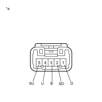
*a Component without harness connected
(Power Window Regulator Switch Assembly)
Remove the power window regulator switch assembly.
-
Measure the resistance when the switch is operated according to the value(s) in the table below.
Standard Resistance Tester Connection Condition Specified Condition 1 (D) - 2 (SD) UP Below 1 Ω 3 (B) - 4 (U) Below 1 Ω 1 (D) - 2 (SD) Off Below 1 Ω 4 (U) - 5 (SU) Below 1 Ω 4 (U) - 5 (SU) DOWN Below 1 Ω 1 (D) - 3 (B) Below 1 Ω Result Proceed to OK NG
NG
REPLACE POWER WINDOW REGULATOR SWITCH ASSEMBLY Click here
OK
-
-
CHECK HARNESS AND CONNECTOR (POWER WINDOW REGULATOR SWITCH ASSEMBLY - FRONT DOOR WINDOW REGULATOR ASSEMBLY (FOR PASSENGER DOOR))
-
Disconnect the G14*1 or H10*2 front door window regulator assembly (for passenger door) connector.
-
*1: for LHD
-
*2: for RHD
-
-
Measure the resistance according to the value(s) in the table below.
Standard Resistance for LHD Tester Connection Condition Specified Condition G9-4 (U) - G14-2 (U) Always Below 1 Ω G9-1 (D) - G14-1 (D) Always Below 1 Ω G9-4 (U) - Body ground Always 10 kΩ or higher G9-1 (D) - Body ground Always 10 kΩ or higher for RHD Tester Connection Condition Specified Condition H9-4 (U) - H10-2 (U) Always Below 1 Ω H9-1 (D) - H10-1 (D) Always Below 1 Ω H9-4 (U) - Body ground Always 10 kΩ or higher H9-1 (D) - Body ground Always 10 kΩ or higher Result Proceed to OK NG
NG
REPAIR OR REPLACE HARNESS OR CONNECTOR
OK
-
-
INSPECT POWER WINDOW REGULATOR MASTER SWITCH ASSEMBLY
-
Remove the power window regulator master switch assembly.
-
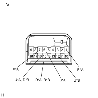
*A w/ Rear Power Window *B w/o Rear Power Window *a Component without harness connected
(Power Window Regulator Master Switch Assembly (for LHD))
for LHD:
Measure the resistance when the switch is operated according to the value(s) in the table below.
Standard Resistance w/ Rear Power Window Tester Connection Condition Specified Condition 6 (B) - 16 (U) UP Below 1 Ω 1 (E) - 15 (D) Below 1 Ω 1 (E) - 16 (U) Off Below 1 Ω 1 (E) - 15 (D) Below 1 Ω 6 (B) - 15 (D) DOWN Below 1 Ω 1 (E) - 16 (U) Below 1 Ω w/o Rear Power Window Tester Connection Condition Specified Condition 15 (B) - 12 (U) UP Below 1 Ω 7 (E) - 16 (D) Below 1 Ω 7 (E) - 12 (U) Off Below 1 Ω 7 (E) - 16 (D) Below 1 Ω 15 (B) - 16 (D) DOWN Below 1 Ω 7 (E) - 12 (U) Below 1 Ω -
*A w/ Rear Power Window *B w/o Rear Power Window *a Component without harness connected
(Power Window Regulator Master Switch Assembly (for RHD))
for RHD:
Measure the resistance when the switch is operated according to the value(s) in the table below.
Standard Resistance w/ Rear Power Window Tester Connection Condition Specified Condition 6 (B) - 12 (U) UP Below 1 Ω 9 (E) - 13 (D) Below 1 Ω 9 (E) - 12 (U) Off Below 1 Ω 9 (E) - 13 (D) Below 1 Ω 6 (B) - 13 (D) DOWN Below 1 Ω 9 (E) - 12 (U) Below 1 Ω w/o Rear Power Window Tester Connection Condition Specified Condition 15 (B) - 12 (U) UP Below 1 Ω 7 (E) - 10 (D) Below 1 Ω 7 (E) - 12 (U) Off Below 1 Ω 7 (E) - 10 (D) Below 1 Ω 15 (B) - 10 (D) DOWN Below 1 Ω 7 (E) - 12 (U) Below 1 Ω Result Proceed to OK NG
NG
REPLACE POWER WINDOW REGULATOR MASTER SWITCH ASSEMBLY Click here
OK
-
-
CHECK HARNESS AND CONNECTOR (POWER WINDOW REGULATOR MASTER SWITCH ASSEMBLY - POWER WINDOW REGULATOR SWITCH ASSEMBLY)
-
Measure the resistance according to the value(s) in the table below.
Standard Resistance for LHD with Rear Power Window Tester Connection Condition Specified Condition H11-16 (U) - G9-5 (SU) Always Below 1 Ω H11-15 (D) - G9-2 (SD) Always Below 1 Ω H11-16 (U) - Body ground Always 10 kΩ or higher H11-15 (D) - Body ground Always 10 kΩ or higher for LHD without Rear Power Window Tester Connection Condition Specified Condition H11-12 (U) - G9-5 (SU) Always Below 1 Ω H11-16 (D) - G9-2 (SD) Always Below 1 Ω H11-12 (U) - Body ground Always 10 kΩ or higher H11-16 (D) - Body ground Always 10 kΩ or higher for RHD with Rear Power Window Tester Connection Condition Specified Condition G11-12 (U) - H9-5 (SU) Always Below 1 Ω G11-13 (D) - H9-2 (SD) Always Below 1 Ω G11-12 (U) - Body ground Always 10 kΩ or higher G11-13 (D) - Body ground Always 10 kΩ or higher for RHD without Rear Power Window Tester Connection Condition Specified Condition G11-12 (U) - H9-5 (SU) Always Below 1 Ω G11-10 (D) - H9-2 (SD) Always Below 1 Ω G11-12 (U) - Body ground Always 10 kΩ or higher G11-10 (D) - Body ground Always 10 kΩ or higher Result Proceed to OK NG
OK
REPLACE FRONT DOOR WINDOW REGULATOR ASSEMBLY (FOR PASSENGER DOOR) Click here
NG
REPAIR OR REPLACE HARNESS OR CONNECTOR
-