LOWER INSTRUMENT PANEL(for Hatchback, Wagon) INSTALLATION
PROCEDURE
-
INSTALL LOWER INSTRUMENT PANEL SUB-ASSEMBLY
-
When using a new lower instrument panel sub-assembly:
-
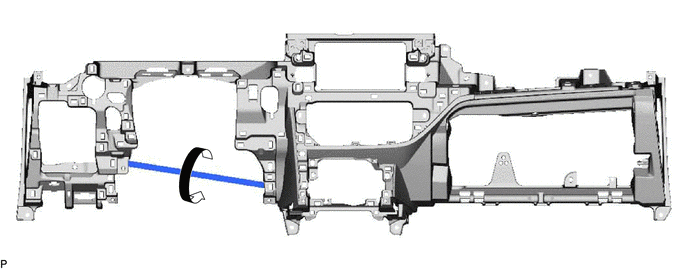
Immediately before installing the lower instrument panel sub-assembly, twist and cut off the portion shown in the illustration.
-
-
Install the lower instrument panel sub-assembly with the 2 bolts <A>, 8 screws <C> and screw <D>.
-
for Automatic Air Conditioning System:
-
Engage the 2 claws to connect the room temperature sensor (cooler thermistor).
-
-
Engage the 2 claws to connect the DLC3.
-
Connect each connector.
-
Engage each clamp.
-
-
CONNECT HOOD LOCK CONTROL LEVER SUB-ASSEMBLY
-
Engage the claw and 2 guides to connect the hood lock control lever sub-assembly.
-
-
INSTALL GLOVE COMPARTMENT DOOR STOPPER SUB-ASSEMBLY
-
Engage the claw to install the glove compartment door stopper sub-assembly.
-
-
INSTALL GLOVE COMPARTMENT DOOR ASSEMBLY
-
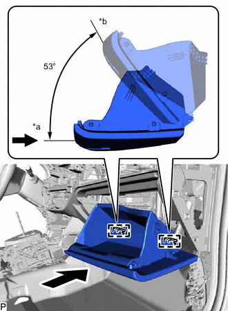
*a Opened Approximately 53° *b Closed With the glove compartment door assembly opened approximately 53° from its closed position, engage the 2 hinges horizontally.
Note
Engaging the hinges from the top will deform the hinges. Be sure to install the glove compartment door assembly horizontally.
-
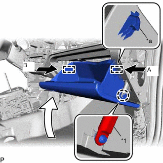
*1 Glove Compartment Door Stopper Sub-assembly *a Stopper Slightly bend the stoppers (A) and (B) in the directions indicated by the arrows in the illustration and engage the stoppers to install the glove compartment door assembly.
-
Engage the claw to connect the glove compartment door stopper sub-assembly.
-
-
INSTALL NO. 2 INSTRUMENT PANEL UNDER COVER SUB-ASSEMBLY (w/ Instrument Panel Under Cover)
-
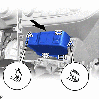
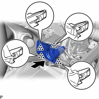
Engage the guide and 3 claws to install the No. 2 instrument panel under cover sub-assembly.
-
-
INSTALL COWL SIDE TRIM BOARD RH
-
INSTALL FRONT DOOR SCUFF PLATE RH
-
INSTALL LOWER CENTER INSTRUMENT PANEL FINISH PANEL
-
Connect each connector.
-
Engage the clamp.
-
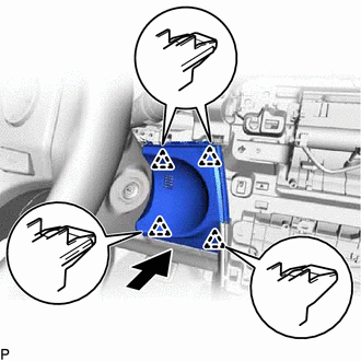
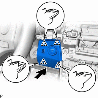
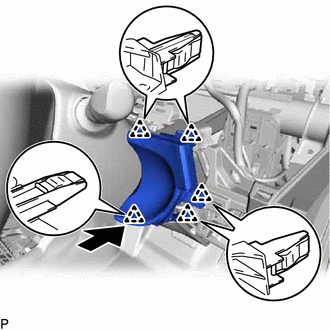
Engage the 3 guides and 2 clips to install the lower center instrument panel finish panel as shown in the illustration.
-
-
INSTALL AIR CONDITIONING CONTROL ASSEMBLY
-
INSTALL NO. 1 NAVIGATION ANTENNA CORD SUB-ASSEMBLY (w/ Navigation System)
-
INSTALL STEREO OPENING COVER WITH BRACKET (w/o Radio Receiver)
-
Connect the connector.
-
Engage the 2 guides.
-
Install the stereo opening cover with bracket with the 4 bolts <B>.
-
-
INSTALL RADIO RECEIVER ASSEMBLY WITH BRACKET (w/ Radio Receiver)
-
INSTALL LOWER INSTRUMENT PANEL FINISH PANEL SUB-ASSEMBLY (w/o Knee Airbag)
-
Engage the 7 clips to install the lower instrument panel finish panel sub-assembly.
-
-
INSTALL LOWER NO. 1 INSTRUMENT PANEL AIRBAG ASSEMBLY (w/ Knee Airbag)
-
INSTALL NO. 1 INSTRUMENT PANEL UNDER COVER SUB-ASSEMBLY (w/ Instrument Panel Under Cover)
-
Engage the guide and claw.
-
Install the No. 1 instrument panel under cover sub-assembly with the 2 screws <E>.
-
-
INSTALL NO. 1 SWITCH HOLE BASE (for LHD)
-
w/o Entry and Start System:
-
Engage the 4 clips to install the No. 1 switch hole base as shown in the illustration.
-
-
w/ Entry and Start System:
-
Connect the connector.
-
Engage the 4 clips to install the No. 1 switch hole base as shown in the illustration.
-
-
-
INSTALL NO. 1 SWITCH HOLE BASE (for RHD)
-
Connect the connector.
-
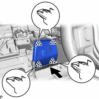
Engage the 4 clips to install the No. 1 switch hole base as shown in the illustration.
-
-
INSTALL NO. 2 SWITCH HOLE BASE (for LHD)
-
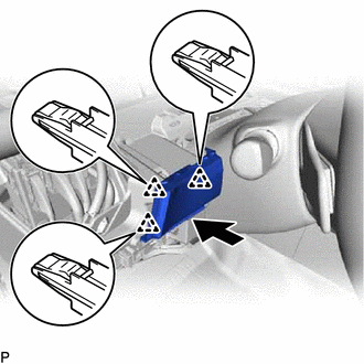
Engage the 3 clips to install the No. 2 switch hole base as shown in the illustration.
-
-
INSTALL NO. 2 SWITCH HOLE BASE (for RHD)
-
w/o Entry and Start System:
-
Engage the 5 clips to install the No. 2 switch hole base as shown in the illustration.
-
-
w/ Entry and Start System:
-
Connect the connector.
-
Engage the 4 clips to install the No. 2 switch hole base as shown in the illustration.
-
-
-
INSTALL LOWER INSTRUMENT CLUSTER FINISH PANEL ASSEMBLY (for LHD)
-
Connect each connector.
-
Engage the 8 clips to install the lower instrument cluster finish panel assembly.
-
-
INSTALL LOWER INSTRUMENT CLUSTER FINISH PANEL ASSEMBLY (for RHD)
-
w/o Entry and Start System:
-
Connect each connector.
-
Engage the claw and 6 clips to install the lower instrument cluster finish panel assembly.
-
-
w/ Entry and Start System:
-
Connect each connector.
-
Engage the 8 clips to install the lower instrument cluster finish panel assembly.
-
-
-
INSTALL COWL SIDE TRIM BOARD LH
-
INSTALL FRONT DOOR SCUFF PLATE LH
-
INSTALL CONSOLE BOX ASSEMBLY
-
INSTALL UPPER INSTRUMENT PANEL ASSEMBLY