COMBUSTION TYPE POWER HEATER SYSTEM Power Heater Switch Circuit
DESCRIPTION
When the heater switch assembly is turned on, the heater assembly sends a drive signal to the heater pump assembly. The heater assembly then receives the fuel necessary for combustion and starts operating.
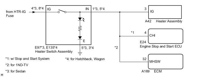
WIRING DIAGRAM
CAUTION / NOTICE / HINT
Note
Inspect the fuses for circuits related to this system before performing the following procedure.
PROCEDURE
-
CONFIRM MODEL
Result Result Proceed to for Sedan A for Hatchback, Wagon B
B 
CHECK HARNESS AND CONNECTOR (HEATER ASSEMBLY - IG POWER SOURCE, BODY GROUND) Click here
A 
-
CHECK HARNESS AND CONNECTOR (HEATER ASSEMBLY - IG POWER SOURCE, BODY GROUND)
-
Disconnect the E97 heater switch assembly connector.
-
Measure the voltage according to the value(s) in the table below.
Standard Voltage Tester Connection Condition Specified Condition E97-4 (IG) - Body ground Ignition switch ON 11 to 14 V E97-4 (IG) - Body ground Ignition switch off Below 1 V -
Measure the resistance according to the value(s) in the table below.
Standard Resistance Tester Connection Condition Specified Condition E97-5 (E) - Body ground Always Below 1 Ω Result Proceed to OK NG
NG 
REPAIR OR REPLACE HARNESS OR CONNECTOR
OK
-
-
INSPECT HEATER SWITCH ASSEMBLY
-
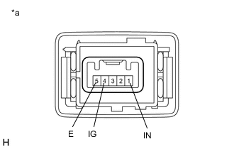
*a Component without harness connected
(Heater Switch Assembly)
Measure the resistance.
-
Measure the resistance according to the value(s) in the table below.
Standard Resistance Tester Connection Condition Specified Condition 4 (IG) - 1 (IN) Heater switch assembly: On Below 1 Ω 4 (IG) - 1 (IN) Heater switch assembly: Off 10 kΩ or higher
-
-
Check the operation indicator.
-
Turn the heater switch assembly on.
-
Connect a positive (+) lead from the battery to terminal 4 (IG) and a negative (-) lead to terminal 5 (E), and check that the operation indicator comes on.
OK Indicator comes on.
Result Proceed to OK NG -
NG
REPLACE HEATER SWITCH ASSEMBLY Click here
OK
-
-
CHECK HARNESS AND CONNECTOR (HEATER SWITCH ASSEMBLY - HEATER ASSEMBLY, ECM, ENGINE STOP AND START ECU)
-
Disconnect the A42 heater assembly connector.
-
Disconnect the E24 engine stop and start ECU connector.*1
-
Disconnect the A169 ECM connector.*2
-
Measure the resistance according to the value(s) in the table below.
Standard Resistance Tester Connection Condition Specified Condition E97-1 (IN) - A42-3 (IG) Always Below 1 Ω E97-1 (IN) - E24-4 (CHI)*1 Always Below 1 Ω E97-1 (IN) - A169-32 (MHSW)*2 Always Below 1 Ω A42-3 (IG) - Body ground Always 10 kΩ or higher E24-4 (CHI) - Body ground*1 Always 10 kΩ or higher A169-32 (MHSW) - Body ground*2 Always 10 kΩ or higher
-
*1: w/ Stop and Start System
-
*2: for 1ND-TV
Result Result Proceed to OK (Resistance between heater assembly and heater switch assembly is normal) A OK (Resistance between heater assembly and ECM is normal) B OK (Resistance between heater assembly and engine stop and start ECU is normal) C NG D -
A
PROCEED TO NEXT SUSPECTED AREA SHOWN IN PROBLEM SYMPTOMS TABLE Click here
B
REPLACE ECM Click here
C
REPLACE ENGINE STOP AND START ECU Click here
D
REPAIR OR REPLACE HARNESS OR CONNECTOR
-
-
CHECK HARNESS AND CONNECTOR (HEATER ASSEMBLY - IG POWER SOURCE, BODY GROUND)
-
Disconnect the E135 heater switch assembly connector.
-
Measure the voltage according to the value(s) in the table below.
Standard Voltage Tester Connection Condition Specified Condition E135-8 (IG) - Body ground Ignition switch ON 11 to 14 V E135-8 (IG) - Body ground Ignition switch off Below 1 V -
Measure the resistance according to the value(s) in the table below.
Standard Resistance Tester Connection Condition Specified Condition E135-3 (E) - Body ground Always Below 1 Ω Result Proceed to OK NG
NG
REPAIR OR REPLACE HARNESS OR CONNECTOR
OK
-
-
INSPECT HEATER SWITCH ASSEMBLY
-
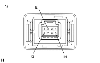
*a Component without harness connected
(Heater Switch Assembly)
Measure the resistance.
-
Measure the resistance according to the value(s) in the table below.
Standard Resistance Tester Connection Condition Specified Condition 8 (IG) - 5 (IN) Heater switch assembly: On Below 1 Ω 8 (IG) - 5 (IN) Heater switch assembly: Off 10 kΩ or higher
-
-
Check the operation indicator.
-
Turn the heater switch assembly on.
-
Connect a positive (+) lead from the battery to terminal 8 (IG) and a negative (-) lead to terminal 3 (E), and check that the operation indicator comes on.
OK Indicator comes on.
Result Proceed to OK NG -
NG
REPLACE HEATER SWITCH ASSEMBLY Click here
OK
-
-
CHECK HARNESS AND CONNECTOR (HEATER SWITCH ASSEMBLY - HEATER ASSEMBLY, ECM, ENGINE STOP AND START ECU)
-
Disconnect the A42 heater assembly connector.
-
Disconnect the E24 engine stop and start ECU connector.*1
-
Disconnect the A169 ECM connector.*2
-
Measure the resistance according to the value(s) in the table below.
Standard Resistance Tester Connection Condition Specified Condition E135-5 (IN) - A42-3 (IG) Always Below 1 Ω E135-5 (IN) - E24-4 (CHI)*1 Always Below 1 Ω E135-5 (IN) - A169-32 (MHSW)*2 Always Below 1 Ω A42-3 (IG) - Body ground Always 10 kΩ or higher E24-4 (CHI) - Body ground*1 Always 10 kΩ or higher A169-32 (MHSW) - Body ground*2 Always 10 kΩ or higher
-
*1: w/ Stop and Start System
-
*2: for 1ND-TV
Result Result Proceed to OK (Resistance between heater assembly and heater switch assembly is normal) A OK (Resistance between heater assembly and ECM is normal) B OK (Resistance between heater assembly and engine stop and start ECU is normal) C NG D -
A
PROCEED TO NEXT SUSPECTED AREA SHOWN IN PROBLEM SYMPTOMS TABLE Click here
B
REPLACE ECM Click here
C
REPLACE ENGINE STOP AND START ECU Click here
D
REPAIR OR REPLACE HARNESS OR CONNECTOR
-