METER / GAUGE SYSTEM Speed Signal Circuit
DESCRIPTION
The combination meter assembly receives the vehicle speed signal from this circuit. The wheel speed sensors produce an output that varies according to the vehicle speed. The wheel speed sensor output is received by the skid control ECU which uses this information to create the vehicle speed sensor signal*a. The vehicle speed sensor signal consists of pulses sent to the combination meter assembly from the skid control ECU. To create this signal, 12 V is output from IG2 which is behind a resistor in the combination meter assembly. This voltage is sent to the skid control ECU. The pulse signal is created by switching the transistor in the skid control ECU on and off, making the voltage on the wire drop to 0 V. A similar system is used for the output of this signal from the combination meter assembly via terminal +S. A voltage of 12 V or 5 V is applied to terminal +S from each ECU or relay that is connected to this terminal. The transistor in the combination meter assembly is controlled by the signal from the skid control ECU. When this transistor is turned on, this transistor makes the voltage supplied by the various ECUs (via their respective internal resistors) drop to 0 V. Each ECU connected to terminal +S of the combination meter assembly controls its respective system based on this pulse signal.
-
*a: This vehicle speed sensor signal is created by the skid control ECU. There is no actual component that is referred to as the vehicle speed sensor. In addition, for some systems, vehicle speed information may be received via CAN communication.
Tech Tips
This circuit is used for the systems connected to terminal +S. This signal is not used for combination meter assembly operation. Combination meter assembly components such as the speedometer operate using data received via CAN communication.
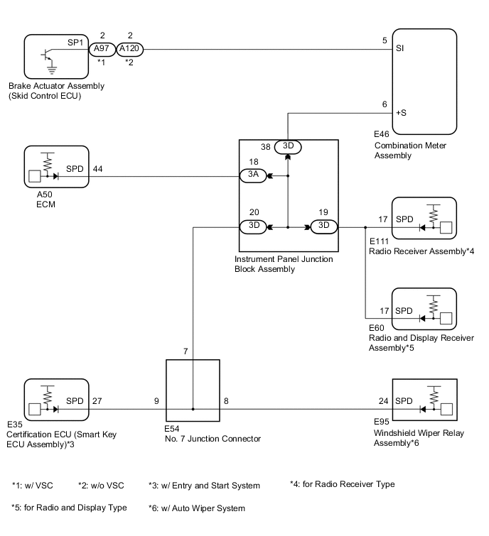
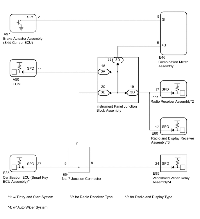
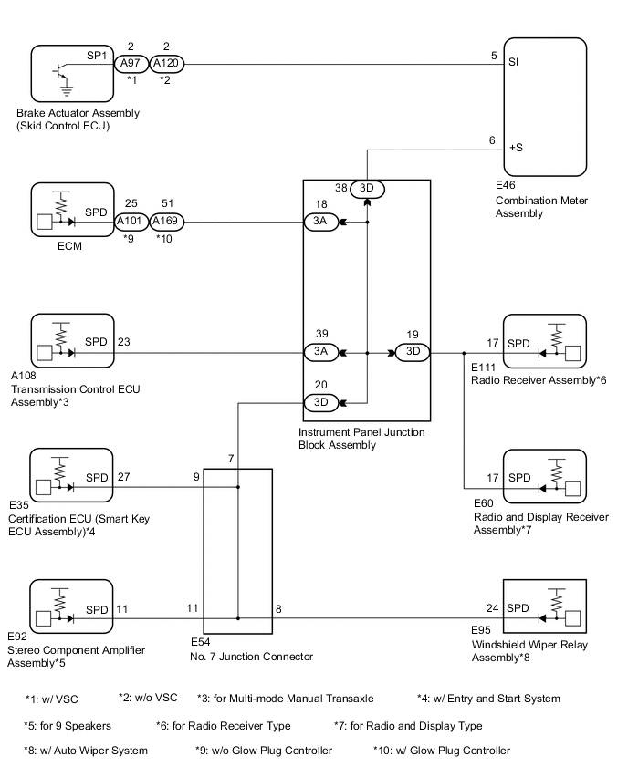
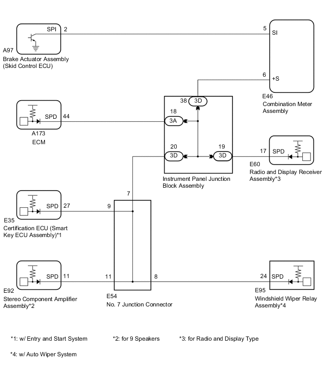
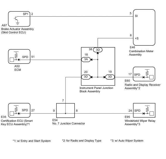
WIRING DIAGRAM
-
for 1NR-FE
-
for 1ZR-FAE
-
for 1ND-TV
-
for 1ZR-FE, 2ZR-FE

-
for 8NR-FTS
-
for 1WW
PROCEDURE
-
INSPECT ECU TERMINAL VOLTAGE (INPUT VOLTAGE)
-
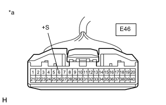
*a Front view of wire harness connector
(to Combination Meter Assembly)
Disconnect the E46 combination meter assembly connector.
-
Measure the voltage according to the value(s) in the table below.
Standard Voltage Tester Connection Condition Specified Condition E46-6 (+S) - Body ground Ignition switch ON 4.5 to 14 V Tech Tips
If any of the ECUs specified in the wiring diagram supplies power to the combination meter assembly, the combination meter assembly will output a waveform.
Result Proceed to OK NG
NG 
CHECK HARNESS AND CONNECTOR (COMBINATION METER ASSEMBLY - INSTRUMENT PANEL JUNCTION BLOCK ASSEMBLY) Click here
OK 
-
-
INSPECT COMBINATION METER ASSEMBLY (OUTPUT VOLTAGE)
-
Reconnect the E46 combination meter assembly connector.
-
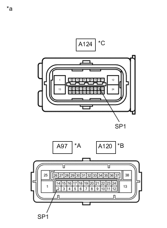
*A w/ VSC *B w/o VSC except 1ZR-FE, 2ZR-FE *C w/o VSC for 1ZR-FE, 2ZR-FE *a Front view of wire harness connector
(to Brake Actuator Assembly (Skid Control ECU))
Disconnect the A97*1, A120*2 or A124*3 brake actuator assembly (skid control ECU) connector.
-
Measure the voltage according to the value(s) in the table below.
Standard Voltage Tester Connection Condition Specified Condition A97-2*1 - Body ground Ignition switch ON 11 to 14 V A120-2*2 - Body ground Ignition switch ON 11 to 14 V A124-22*3 - Body ground Ignition switch ON 11 to 14 V
-
*1: w/ VSC
-
*2: w/o VSC except 1ZR-FE, 2ZR-FE
-
*3: w/o VSC for 1ZR-FE, 2ZR-FE
Result Proceed to OK NG -
NG
CHECK HARNESS AND CONNECTOR (COMBINATION METER ASSEMBLY - BRAKE ACTUATOR ASSEMBLY (SKID CONTROL ECU)) Click here
OK
-
-
INSPECT SKID CONTROL ECU (INPUT WAVEFORM)
-
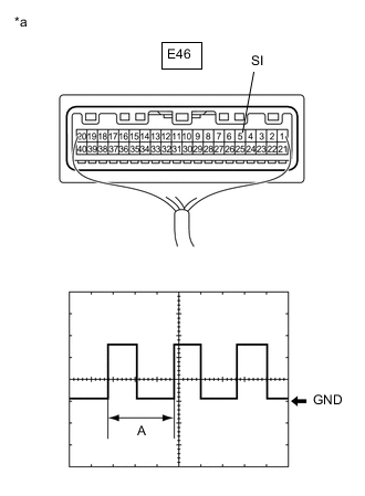
*a Component with harness connected
(Combination Meter Assembly)
Check the input waveform.
-
Reconnect the A97*1, A120*2 or A124*3 brake actuator assembly (skid control ECU) connector.
-
*1: w/ VSC
-
*2: w/o VSC except 1ZR-FE, 2ZR-FE
-
*3: w/o VSC for 1ZR-FE, 2ZR-FE
-
-
Remove the combination meter assembly with the connector(s) still connected.
-
Connect an oscilloscope to terminal E46-5 (SI) and body ground.
-
Turn the ignition switch to ON.
-
Turn a wheel slowly.
-
Check the signal waveform according to the condition(s) in the table below.
Item Condition Tool setting 5 V/DIV., 20 ms./DIV. Vehicle condition Ignition switch ON, wheel being rotated OK The waveform is similar to that shown in the illustration. Tech Tips
When the system is functioning normally, one wheel revolution generates 4 pulses. As the vehicle speed increases, the width indicated by (A) in the illustration narrows.
Result Proceed to OK NG -
OK 
REPLACE COMBINATION METER ASSEMBLY for Hatchback, Wagon: Click here
REPLACE COMBINATION METER ASSEMBLY for Sedan: Click hereNG
REPLACE BRAKE ACTUATOR ASSEMBLY (SKID CONTROL ECU) Click here
-
-
CHECK HARNESS AND CONNECTOR (COMBINATION METER ASSEMBLY - BRAKE ACTUATOR ASSEMBLY (SKID CONTROL ECU))
-
Disconnect the E46 combination meter assembly connector.
-
Disconnect the A97*1, A120*2 or A124*3 brake actuator assembly (skid control ECU) connector.
-
Measure the resistance according to the value(s) in the table below.
Standard Resistance Tester Connection Condition Specified Condition E46-5 (SI) - A97-2 (SP1)*1 Always Below 1 Ω E46-5 (SI) - A120-2*2 Always Below 1 Ω E46-5 (SI) - A124-22*3 Always Below 1 Ω E46-5 (SI) - Body ground Always 10 kΩ or higher
-
*1: w/ VSC
-
*2: w/o VSC except 1ZR-FE, 2ZR-FE
-
*3: w/o VSC for 1ZR-FE, 2ZR-FE
Result Proceed to OK NG -
OK
REPLACE COMBINATION METER ASSEMBLY for Hatchback, Wagon: Click here
REPLACE COMBINATION METER ASSEMBLY for Sedan: Click hereNG
REPAIR OR REPLACE HARNESS OR CONNECTOR
-
-
CHECK HARNESS AND CONNECTOR (COMBINATION METER ASSEMBLY - INSTRUMENT PANEL JUNCTION BLOCK ASSEMBLY)
-
Disconnect the 3D instrument panel junction block assembly connector.
-
Measure the resistance according to the value(s) in the table below.
Standard Resistance Tester Connection Condition Specified Condition E46-6 (+S) - 3D-38 Always Below 1 Ω E46-6 (+S) - Body ground Always 10 kΩ or higher Result Proceed to OK NG
NG
REPAIR OR REPLACE HARNESS OR CONNECTOR
OK
-
-
CHECK HARNESS AND CONNECTOR (INSTRUMENT PANEL JUNCTION BLOCK ASSEMBLY)
-
Inspect for a short in the wire harness and connectors connected to the instrument panel junction block assembly shown in the wiring diagram.
Tech Tips
If voltage is not present, it is possible that an ECU or circuit has a malfunction. The malfunctioning ECU or circuit will be diagnosed in the following steps.
-
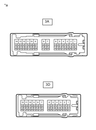
*a Component without harness connected
(Instrument Panel Junction Block Assembly)
Disconnect the 3A and 3D instrument panel junction block assembly connector.
-
Measure the voltage according to the value(s) in the table below.
Standard Voltage Tester Connection Condition Specified Condition 3A-18 - Body ground Ignition switch ON 4.5 to 14 V 3A-39*1 - Body ground Ignition switch ON 4.5 to 14 V 3D-19*2 - Body ground Ignition switch ON 4.5 to 14 V 3D-20*3 - Body ground Ignition switch ON 4.5 to 14 V
-
*1: for Multi-mode Manual Transaxle
-
*2: for Radio Receiver Type, for Radio and Display Type
-
*3: w/ Entry and Start System, for 9 Speakers, w/ Auto Wiper System
-
Result Result Proceed to Voltage is not present in one circuit. A Voltage is present in all of the circuits. B -
B
REPLACE INSTRUMENT PANEL JUNCTION BLOCK ASSEMBLY for LHD: Click here
REPLACE INSTRUMENT PANEL JUNCTION BLOCK ASSEMBLY for RHD: Click hereA
-
-
SYSTEM CHECK
-
Select the circuit for which voltage was not present in step 6.
Result Tester Connection System that Uses the Circuit Proceed to 3A-18 - Body ground SFI system*1 or ECD system*2 A 3A-39 - Body ground Multi-mode manual transaxle system*3 B 3D-19 - Body ground Audio and visual system*4 or Navigation system*5 C 3D-20 - Body ground - D
-
*1: for Gasoline
-
*2: for Diesel
-
*3: for Multi-mode Manual Transaxle
-
*4: w/o Navigation System
-
*5: w/ Navigation System
-
B
CHECK HARNESS AND CONNECTOR (TRANSMISSION CONTROL ECU ASSEMBLY CIRCUIT) Click here
C
CHECK HARNESS AND CONNECTOR (RADIO RECEIVER ASSEMBLY CIRCUIT, RADIO AND DISPLAY RECEIVER ASSEMBLY CIRCUIT) Click here
D
CHECK HARNESS AND CONNECTOR (INSTRUMENT PANEL JUNCTION BLOCK ASSEMBLY - JUNCTION CONNECTOR) Click here
A
-
-
CHECK HARNESS AND CONNECTOR (ECM CIRCUIT)
-
Disconnect the A50*1, A101*2, A169*3 or A173*4 ECM connector.
-
*1: for 1NR-FE, 1ZR-FAE, 1ZR-FE, 2ZR-FE, 1WW
-
*2: for 1ND-TV without Glow Plug Controller
-
*3: for 1ND-TV with Glow Plug Controller
-
*4: for 8NR-FTS
-
-
Measure the resistance according to the value(s) in the table below.
Standard Resistance Tester Connection Condition Specified Condition A50-44 (SPD)*1 - Body ground Always 10 kΩ or higher A50-51 (SPD)*2 - Body ground Always 10 kΩ or higher A101-25 (SPD)*3 - Body ground Always 10 kΩ or higher A169-51 (SPD)*4 - Body ground Always 10 kΩ or higher A173-44 (SPD)*5 - Body ground Always 10 kΩ or higher
-
*1: for 1NR-FE, 1ZR-FAE, 1ZR-FE, 2ZR-FE
-
*2: for 1WW
-
*3: for 1ND-TV without Glow Plug Controller
-
*4: for 1ND-TV with Glow Plug Controller
-
*5: for 8NR-FTS
Result Proceed to OK NG -
OK
REPLACE ECM for 1NR-FE: Click here
REPLACE ECM for 1ZR-FAE: Click here
REPLACE ECM for 1ZR-FE: Click here
REPLACE ECM for 2ZR-FE: Click here
REPLACE ECM for 1ND-TV (w/o Glow Plug Controller): Click here
REPLACE ECM for 1ND-TV (w/ Glow Plug Controller): Click here
REPLACE ECM for 8NR-FTS: Click here
REPLACE ECM for 1WW: Click hereNG
REPAIR OR REPLACE HARNESS OR CONNECTOR
-
-
CHECK HARNESS AND CONNECTOR (TRANSMISSION CONTROL ECU ASSEMBLY CIRCUIT)
-
Disconnect the A108 transmission control ECU assembly connector.
-
Measure the resistance according to the value(s) in the table below.
Standard Resistance Tester Connection Condition Specified Condition A108-23 (SPD) - Body ground Always 10 kΩ or higher Result Proceed to OK NG
OK
REPLACE TRANSMISSION CONTROL ECU ASSEMBLY Click here
NG
REPAIR OR REPLACE HARNESS OR CONNECTOR
-
-
CHECK HARNESS AND CONNECTOR (RADIO RECEIVER ASSEMBLY CIRCUIT, RADIO AND DISPLAY RECEIVER ASSEMBLY CIRCUIT)
-
Disconnect the E111 radio receiver assembly*1 or E60 radio and display receiver assembly*2 connector.
-
Measure the resistance according to the value(s) in the table below.
Standard Resistance Tester Connection Condition Specified Condition E111-17 (SPD)*1 - Body ground Always 10 kΩ or higher E60-17 (SPD)*2 - Body ground Always 10 kΩ or higher
-
*1: for Radio Receiver Type
-
*2: for Radio and Display Type
Result Result Proceed to OK (for Radio Receiver Type) A OK (for Radio and Display Type) B NG C -
A
REPLACE RADIO RECEIVER ASSEMBLY for Hatchback, Wagon: Click here
REPLACE RADIO RECEIVER ASSEMBLY for Sedan: Click hereB
REPLACE RADIO AND DISPLAY RECEIVER ASSEMBLY Click here
C
REPAIR OR REPLACE HARNESS OR CONNECTOR
-
-
CHECK HARNESS AND CONNECTOR (INSTRUMENT PANEL JUNCTION BLOCK ASSEMBLY - JUNCTION CONNECTOR)
-
Disconnect the E54 junction connector.
-
Measure the resistance according to the value(s) in the table below.
Standard Resistance Tester Connection Condition Specified Condition 3D-20 - E54-7 Always Below 1 Ω 3D-20 - Body ground Always 10 kΩ or higher Result Proceed to OK NG
NG
REPAIR OR REPLACE HARNESS OR CONNECTOR
OK
-
-
CHECK HARNESS AND CONNECTOR (NO. 7 JUNCTION CONNECTOR)
-
Inspect for a short in the wire harness and connectors connected to the No. 7 junction connector shown in the wiring diagram.
Tech Tips
If voltage is not present, it is possible that an ECU or circuit has a malfunction. The malfunctioning ECU or circuit will be diagnosed in the following steps.
-
Measure the voltage according to the value(s) in the table below.
Standard Voltage Tester Connection Condition Specified Condition E54-8 - Body ground Ignition switch ON 4.5 to 14 V E54-9 - Body ground Ignition switch ON 4.5 to 14 V E54-11 - Body ground Ignition switch ON 4.5 to 14 V
Result Result Proceed to Voltage is not present in one circuit. A Voltage is present in all of the circuits. B -
B
REPLACE JUNCTION CONNECTOR (INSTRUMENT PANEL WIRE)
A
-
-
SYSTEM CHECK
-
Select the circuit for which voltage was not present in step 12.
Result Tester Connection System that Uses the Circuit Proceed to E54-8 - Body ground Auto wiper system*1 A E54-9 - Body ground Entry and start system*2 B E54-11 - Body ground Navigation system*3 C
-
*1: w/ Auto Wiper System
-
*2: w/ Entry and Start System
-
*3: for 9 Speakers
-
B
CHECK HARNESS AND CONNECTOR (CERTIFICATION ECU (SMART KEY ECU ASSEMBLY) CIRCUIT) Click here
C
CHECK HARNESS AND CONNECTOR (STEREO COMPONENT AMPLIFIER ASSEMBLY CIRCUIT) Click here
A
-
-
CHECK HARNESS AND CONNECTOR (WINDSHIELD WIPER RELAY ASSEMBLY CIRCUIT)
-
Disconnect the E95 windshield wiper relay assembly connector.
-
Measure the resistance according to the value(s) in the table below.
Standard Resistance Tester Connection Condition Specified Condition E95-24 (SPD) - Body ground Always 10 kΩ or higher Result Proceed to OK NG
OK
REPLACE WINDSHIELD WIPER RELAY ASSEMBLY for LHD: Click here
REPLACE WINDSHIELD WIPER RELAY ASSEMBLY for RHD: Click hereNG
REPAIR OR REPLACE HARNESS OR CONNECTOR
-
-
CHECK HARNESS AND CONNECTOR (CERTIFICATION ECU (SMART KEY ECU ASSEMBLY) CIRCUIT)
-
Disconnect the E35 certification ECU (smart key ECU assembly) connector.
-
Measure the resistance according to the value(s) in the table below.
Standard Resistance Tester Connection Condition Specified Condition E35-27 (SPD) - Body ground Always 10 kΩ or higher Result Proceed to OK NG
OK
REPLACE CERTIFICATION ECU (SMART KEY ECU ASSEMBLY)
NG
REPAIR OR REPLACE HARNESS OR CONNECTOR
-
-
CHECK HARNESS AND CONNECTOR (STEREO COMPONENT AMPLIFIER ASSEMBLY CIRCUIT)
-
Disconnect the E92 stereo component amplifier assembly connector.
-
Measure the resistance according to the value(s) in the table below.
Standard Resistance Tester Connection Condition Specified Condition E92-11 (SPD) - Body ground Always 10 kΩ or higher Result Proceed to OK NG
OK
REPLACE STEREO COMPONENT AMPLIFIER ASSEMBLY Click here
NG
REPAIR OR REPLACE HARNESS OR CONNECTOR
-