REAR AXLE CARRIER REMOVAL
CAUTION / NOTICE / HINT
Tech Tips
-
Use the same procedure for the RH side and LH side.
-
The procedure listed below is for the LH side.
PROCEDURE
-
REMOVE REAR WHEEL
-
REMOVE UPPER CONSOLE PANEL SUB-ASSEMBLY
-
LOOSEN NO. 2 WIRE ADJUSTING NUT
-
REMOVE REAR SUSPENSION ARM COVER
-
REMOVE REAR FLOOR SIDE MEMBER COVER LH (for LH Side)
-
REMOVE REAR FLOOR SIDE MEMBER COVER RH (for RH Side)
-
REMOVE PARKING BRAKE LEVER PROTECTOR
-
SEPARATE NO. 3 PARKING BRAKE CABLE ASSEMBLY
-
SEPARATE REAR DISC BRAKE CALIPER ASSEMBLY
-
REMOVE REAR DISC
-
REMOVE REAR HEIGHT CONTROL SENSOR SUB-ASSEMBLY (w/ Height Control Sensor)
-
DISCONNECT SKID CONTROL SENSOR WIRE
-
REMOVE REAR AXLE HUB AND BEARING ASSEMBLY
-
REMOVE REAR NO. 1 SUSPENSION ARM ASSEMBLY
-
REMOVE REAR AXLE CARRIER SUB-ASSEMBLY
-
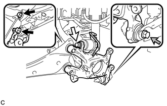

Bolt (A) 
Bolt (B) 
Bolt (C) Loosen the 2 bolts (A), bolt (B) and bolt (C).
Note
-
Because the nuts have their own stoppers, do not turn the nuts. Loosen the bolts with the nuts secured.
-
Do not remove the bolts.
-
-
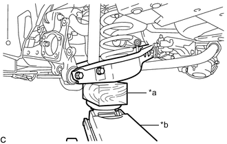
*a Wooden Block *b Jack Using a jack and wooden block, keep the rear No. 2 suspension arm assembly level.
CAUTION:
Do not jack up the rear No. 2 suspension arm assembly too high as the vehicle may fall.
Note
-
When jacking up the rear No. 2 suspension arm assembly, be sure to jack it up slowly.
-
Make sure to perform this operation with the vehicle kept as low as possible.
-
-
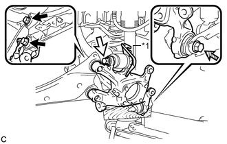
*1 No. 2 Flexible Hose Bracket Bolt (A) Bolt (B) Bolt (C) Remove the 2 bolts (A), and separate the rear trailing arm assembly from the rear axle carrier sub-assembly.
-
Remove the bolt (B), nut and No. 2 flexible hose bracket, and then separate the rear upper control arm assembly from the rear axle carrier sub-assembly.
Note
Because the nut has its own stopper, do not turn the nut. Loosen the bolt with the nut secured.
-
Remove the bolt (C), nut and rear axle carrier sub-assembly from the rear No. 2 suspension arm assembly.
Note
Because the nut has its own stopper, do not turn the nut. Loosen the bolt with the nut secured.
-