MULTI-MODE MANUAL TRANSAXLE SYSTEM, Diagnostic DTC:P0821
| DTC Code | DTC Name |
|---|---|
| P0821 | Gear Lever "X" Position Circuit |
DESCRIPTION
Based on the signal from the transmission shift main switch, the TCM detects whether the shift lever is in E or M. If the shift lever position switch is ON despite the shift lever being in N or R, the TCM stores this DTC.
For more details of the transmission shift main switch, refer to DTC P0820.
| DTC No. | Detection Item | DTC Detection Condition | Trouble Area | MIL | Warning Indicate | Memory |
|---|---|---|---|---|---|---|
| P0821 | Gear Lever "X" Position Circuit | The TCM detects the following conditions simultaneously for 1.0 second: (1-trip detection logic)
|
|
Does not come on | Comes on | DTC stored |
WIRING DIAGRAM
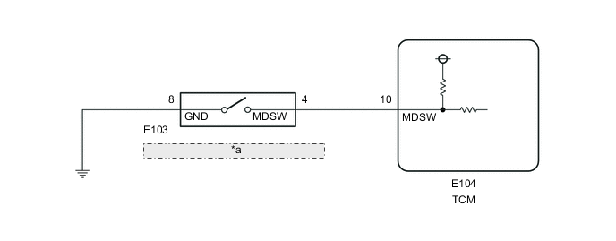
| *a | Shift Lock Control Unit Assembly (Transmission Shift Main Switch) |
PROCEDURE
-
INSPECT SHIFT LOCK CONTROL UNIT ASSEMBLY (TRANSMISSION SHIFT MAIN SWITCH)
-
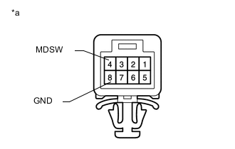
*a Component without harness connected
Shift Lock Control Unit Assembly
(Transmission Shift Main Switch)
Disconnect the shift lock control unit connector.
-
Measure the resistance according to the value(s) in the table below.
Standard Resistance Tester Connection Condition Specified Condition 4 (MDSW) - 8 (GND) Shift lever in R, N or E 10 kΩ or higher Shift lever in M, "+" or "-" Below 1 Ω Result Proceed to OK NG
NG 
REPLACE SHIFT LOCK CONTROL UNIT ASSEMBLY Click here
OK 
-
-
CHECK HARNESS AND CONNECTOR (SHIFT LOCK CONTROL UNIT ASSEMBLY - TCM)
-
Disconnect the TCM connector.
-
Measure the resistance according to the value(s) in the table below.
Standard Resistance Tester Connection Condition Specified Condition E104-10 (MDSW) - E103-4 (MDSW) Always Below 1 Ω E104-10 (MDSW) - Body ground Always 10 kΩ or higher Result Proceed to OK NG
NG
REPAIR OR REPLACE HARNESS OR CONNECTOR
OK
-
-
CHECK HARNESS AND CONNECTOR (SHIFT LOCK CONTROL UNIT ASSEMBLY - BODY GROUND)
-
Measure the resistance according to the value(s) in the table below.
Standard Resistance Tester Connection Condition Specified Condition E103-8 (GND) - Body ground Always Below 1 Ω Result Proceed to OK NG
NG
REPAIR OR REPLACE HARNESS OR CONNECTOR
OK
-
-
REPLACE TCM
-
Replace the TCM.
Result Proceed to NEXT
NEXT
-
-
PERFORM INITIALIZATION
-
Perform the initialization and learning procedure.
Result Proceed to NEXT
NEXT
END
-