MANUAL TRANSAXLE ASSEMBLY REMOVAL
CAUTION / NOTICE / HINT
Note
When the manual transaxle assembly is removed, be sure to use a new clutch release with bearing cylinder assembly and new installation bolts. Removal of the transaxle allows the compressed clutch release with bearing cylinder assembly to return to its original position. Dust from the moving section may damage the seal of the clutch release with bearing cylinder assembly, possibly causing clutch fluid leaks.
PROCEDURE
-
REMOVE ENGINE ASSEMBLY WITH TRANSAXLE (w/ Glow Plug Controller)
-
REMOVE ENGINE ASSEMBLY WITH TRANSAXLE (w/o Glow Plug Controller)
-
REMOVE FRONT ENGINE MOUNTING INSULATOR (w/ Glow Plug Controller)
-
REMOVE FRONT ENGINE MOUNTING INSULATOR (w/o Glow Plug Controller)
-
REMOVE REAR ENGINE MOUNTING INSULATOR (w/ Glow Plug Controller)
-
REMOVE REAR ENGINE MOUNTING INSULATOR (w/o Glow Plug Controller)
-
REMOVE NO. 1 AIR TUBE
-
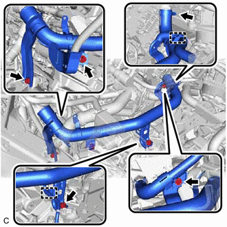
Disconnect the 2 wire harness clamps from the manual transaxle assembly.
-
Remove the 4 bolts.
-
Loosen the hose clamp and remove the No. 1 air tube.
-
-
REMOVE STARTER ASSEMBLY (w/ Stop And Start System)
-
REMOVE STARTER ASSEMBLY (w/o Stop And Start System)
-
DISCONNECT WIRE HARNESS (w/ Stop And Start System)
-
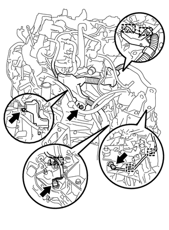
Disengage the 5 clamps.
-
Disconnect the back-up light switch assembly connector.
-
Disconnect the park/neutral position switch assembly connector.
-
Remove the nut and bolt, and disconnect the wire harness from the manual transaxle assembly.
-
-
DISCONNECT WIRE HARNESS (w/o Stop And Start System)
-
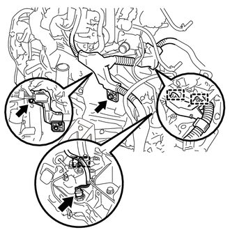
Disengage the 3 clamps.
-
Disconnect the back-up light switch assembly connector.
-
Remove the nut and bolt, and disconnect the wire harness from the manual transaxle assembly.
-
-
REMOVE MANUAL TRANSAXLE ASSEMBLY
-
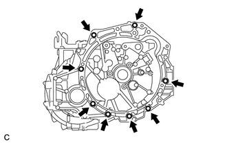
Remove the 8 bolts and manual transaxle assembly.
-
-
REMOVE FRONT ENGINE MOUNTING BRACKET
-
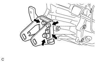
Remove the 4 bolts and front engine mounting bracket.
-
-
REMOVE ENGINE MOUNTING BRACKET LH
-
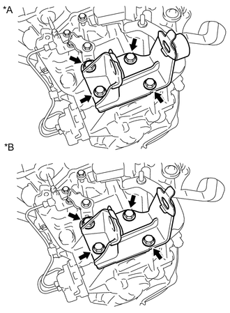
*A Type A *B Type B Remove the 4 bolts and engine mounting bracket LH.
-
-
REMOVE REAR ENGINE MOUNTING BRACKET
-
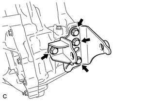
Remove the 4 bolts and rear engine mounting bracket.
-
-
REMOVE CLUTCH ACCUMULATOR ASSEMBLY
-
REMOVE CLUTCH RELEASE BLEEDER SUB-ASSEMBLY
-
REMOVE CLUTCH RELEASE WITH BEARING CYLINDER ASSEMBLY
-
REMOVE CLUTCH RELEASE CYLINDER TO BLEEDER TUBE
-
REMOVE WIRE HARNESS CLAMP BRACKET
-
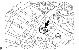
Remove the bolt and wire harness clamp bracket.
-
-
REMOVE SPEEDOMETER DRIVEN HOLE COVER SUB-ASSEMBLY
-
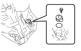
Remove the bolt and speedometer driven hole cover sub-assembly from the manual transaxle assembly.
-
Remove the O-ring from the speedometer driven hole cover sub-assembly.
-