LIN COMMUNICATION SYSTEM, Diagnostic DTC:B2321
| DTC Code | DTC Name |
|---|---|
| B2321 | Driver Side Door ECU Communication Stop |
DESCRIPTION
This DTC is stored when LIN communication between the front door window regulator assembly (for driver door) and main body ECU (multiplex network body ECU) stops for 10 seconds or more.
| DTC No. | Detection Item | DTC Detection Condition | Trouble Area |
|---|---|---|---|
| B2321 | Driver Side Door ECU Communication Stop | No communication between front door window regulator assembly (for driver door) and main body ECU (multiplex network body ECU) for 10 seconds or more. |
|
-
*1: for Models with Jam Protection Function on 4 Windows
-
*2: for Models with Jam Protection Function on Driver Door Window Only
WIRING DIAGRAM
-
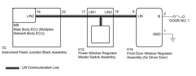
for Models with Jam Protection Function on 4 Windows
-
for LHD
-
for RHD

-
-
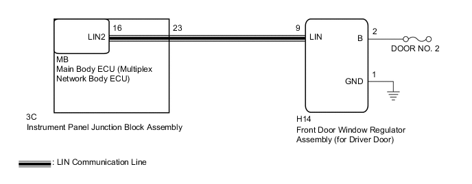
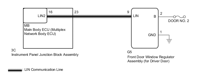
for Models with Jam Protection Function on Driver Door Window Only
-
for LHD
-
for RHD
-
CAUTION / NOTICE / HINT
Note
-
Inspect the fuses for circuits related to this system before performing the following procedure.
-
When a front door window regulator assembly is replaced or removed and reinstalled, it requires initialization.
for Models with Jam Protection Function on 4 Windows: Click here
for Models with Jam Protection Function on Driver Door Window Only: Click here
PROCEDURE
-
SYSTEM CHECK
-
Check the vehicle specifications.
Result Result Proceed to for Models with Jam Protection Function on 4 Windows A for Models with Jam Protection Function on Driver Door Window Only B
B 
CHECK HARNESS AND CONNECTOR (INSTRUMENT PANEL JUNCTION BLOCK ASSEMBLY - FRONT DOOR WINDOW REGULATOR ASSEMBLY (for Driver Door)) Click here
A 
-
-
CHECK DTC OUTPUT
-
Clear the DTCs.
Body Electrical > Main Body > Clear DTCs -
Recheck for DTCs.
Body Electrical > Main Body > Trouble CodesResult Result Proceed to Only DTC B2321 is output. A DTC B1206 and B2321 are output simultaneously. B Tech Tips
When DTC B1206 and B2321 are output simultaneously, perform troubleshooting for DTC B1206 first.
B 
GO TO DTC B1206 Click here
A
-
-
CHECK HARNESS AND CONNECTOR (POWER WINDOW REGULATOR MASTER SWITCH ASSEMBLY - FRONT DOOR WINDOW REGULATOR ASSEMBLY (for Driver Door))
-
for LHD
-
Disconnect the H12 power window regulator master switch assembly connector.
-
Disconnect the H14 front door window regulator assembly (for driver door) connector.
-
Measure the resistance according to the value(s) in the table below.
Standard Resistance Tester Connection Condition Specified Condition H12-16 (LIN2) - H14-9 (LIN) Always Below 1 Ω H12-16 (LIN2) - Body ground Always 10 kΩ or higher H14-9 (LIN) - Body ground Always 10 kΩ or higher
-
-
for RHD
-
Disconnect the G3 power window regulator master switch assembly connector.
-
Disconnect the G5 front door window regulator assembly (for driver door) connector.
-
Measure the resistance according to the value(s) in the table below.
Standard Resistance Tester Connection Condition Specified Condition G3-16 (LIN2) - G5-9 (LIN) Always Below 1 Ω G3-16 (LIN2) - Body ground Always 10 kΩ or higher G5-9 (LIN) - Body ground Always 10 kΩ or higher
Result Proceed to OK NG -
NG
REPAIR OR REPLACE HARNESS OR CONNECTOR
OK
-
-
INSPECT POWER WINDOW REGULATOR MASTER SWITCH ASSEMBLY
-
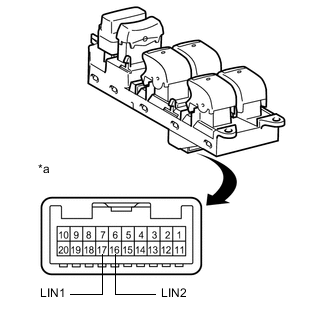
*a Component without harness connected
(Power Window Regulator Master Switch Assembly)
Remove the power window regulator master switch assembly.
-
Measure the resistance according to the value(s) in the table below.
Standard Resistance Tester Connection Condition Specified Condition 16 (LIN2) - 17 (LIN1) Always Below 1 Ω Result Proceed to OK NG
NG
REPLACE POWER WINDOW REGULATOR MASTER SWITCH ASSEMBLY Click here
OK
-
-
CHECK HARNESS AND CONNECTOR (FRONT DOOR WINDOW REGULATOR ASSEMBLY (for Driver Door) - BATTERY, BODY GROUND)
-
for LHD
-
Measure the voltage according to the value(s) in the table below.
Standard Voltage Tester Connection Condition Specified Condition H14-2 (B) - H14-1 (GND) Always 11 to 14 V -
Measure the resistance according to the value(s) in the table below.
Standard Resistance Tester Connection Condition Specified Condition H14-1 (GND) - Body ground Always Below 1 Ω
-
-
for RHD
-
Measure the voltage according to the value(s) in the table below.
Standard Voltage Tester Connection Condition Specified Condition G5-2 (B) - G5-1 (GND) Always 11 to 14 V -
Measure the resistance according to the value(s) in the table below.
Standard Resistance Tester Connection Condition Specified Condition G5-1 (GND) - Body ground Always Below 1 Ω
Result Proceed to OK NG -
NG
REPAIR OR REPLACE HARNESS OR CONNECTOR
OK
-
-
REPLACE FRONT DOOR WINDOW REGULATOR ASSEMBLY (for Driver Door)
-
Replace the front door window regulator assembly (for driver door).
Result Proceed to NEXT
NEXT
-
-
CHECK DTC OUTPUT
-
Clear the DTCs.
Body Electrical > Main Body > Clear DTCs -
Recheck for DTCs.
Body Electrical > Main Body > Trouble CodesOK DTC B2321 is not output. Result Proceed to OK NG
OK
END (FRONT DOOR WINDOW REGULATOR ASSEMBLY (for Driver Door) WAS DEFECTIVE)
NG
REPLACE MAIN BODY ECU (MULTIPLEX NETWORK BODY ECU) for LHD: Click here
REPLACE MAIN BODY ECU (MULTIPLEX NETWORK BODY ECU) for RHD: Click here -
-
CHECK HARNESS AND CONNECTOR (INSTRUMENT PANEL JUNCTION BLOCK ASSEMBLY - FRONT DOOR WINDOW REGULATOR ASSEMBLY (for Driver Door))
-
for LHD
-
Disconnect the 3C instrument panel junction block assembly connector.
-
Disconnect the H14 front door window regulator assembly (for driver door) connector.
-
Measure the resistance according to the value(s) in the table below.
Standard Resistance Tester Connection Condition Specified Condition 3C-23 - H14-9 (LIN) Always Below 1 Ω H14-9 (LIN) - Body ground Always 10 kΩ or higher 3C-23 - Body ground Always 10 kΩ or higher
-
-
for RHD
-
Disconnect the 3C instrument panel junction block assembly connector.
-
Disconnect the G5 front door window regulator assembly (for driver door) connector.
-
Measure the resistance according to the value(s) in the table below.
Standard Resistance Tester Connection Condition Specified Condition 3C-23 - G5-9 (LIN) Always Below 1 Ω G5-9 (LIN) - Body ground Always 10 kΩ or higher 3C-23 - Body ground Always 10 kΩ or higher
Result Proceed to OK NG -
NG
REPAIR OR REPLACE HARNESS OR CONNECTOR
OK
-
-
INSPECT INSTRUMENT PANEL JUNCTION BLOCK ASSEMBLY
-
Remove the instrument panel junction block assembly.
for LHD: Click here
for RHD: Click here
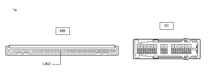
*a Component without harness connected
(Instrument Panel Junction Block Assembly)
- - -
Remove the main body ECU (multiplex network body ECU) from the instrument panel junction block assembly.
-
Measure the resistance according to the value(s) in the table below.
Tech Tips
This inspection is to check the LIN communication line in the instrument panel junction block assembly that connects the wire harness to the built-in main body ECU (multiplex network body ECU).
Standard Resistance Tester Connection Condition Specified Condition 3C-23 - MB-16 (LIN2) Always Below 1 Ω Result Proceed to OK NG
NG
REPLACE INSTRUMENT PANEL JUNCTION BLOCK ASSEMBLY for LHD: Click here
REPLACE INSTRUMENT PANEL JUNCTION BLOCK ASSEMBLY for RHD: Click hereOK
-
-
CHECK HARNESS AND CONNECTOR (FRONT DOOR WINDOW REGULATOR ASSEMBLY (for Driver Door) - BATTERY, BODY GROUND)
-
for LHD
-
Measure the voltage according to the value(s) in the table below.
Standard Voltage Tester Connection Condition Specified Condition H14-2 (B) - H14-1 (GND) Always 11 to 14 V -
Measure the resistance according to the value(s) in the table below.
Standard Resistance Tester Connection Condition Specified Condition H14-1 (GND) - Body ground Always Below 1 Ω
-
-
for RHD
-
Measure the voltage according to the value(s) in the table below.
Standard Voltage Tester Connection Condition Specified Condition G5-2 (B) - G5-1 (GND) Always 11 to 14 V -
Measure the resistance according to the value(s) in the table below.
Standard Resistance Tester Connection Condition Specified Condition G5-1 (GND) - Body ground Always Below 1 Ω
Result Proceed to OK NG -
NG
REPAIR OR REPLACE HARNESS OR CONNECTOR
OK
-
-
REPLACE FRONT DOOR WINDOW REGULATOR ASSEMBLY (for Driver Door)
-
Replace the front door window regulator assembly (for driver door).
for Sedan: Click here
except Sedan: Click here
Result Proceed to NEXT
NEXT
-
-
CHECK DTC OUTPUT
-
Clear the DTCs.
Body Electrical > Main Body > Clear DTCs -
Recheck for DTCs.
Body Electrical > Main Body > Trouble CodesOK DTC B2321 is not output. Result Proceed to OK NG
OK
END (FRONT DOOR WINDOW REGULATOR ASSEMBLY (for DRIVER DOOR) WAS DEFECTIVE)
NG
REPLACE MAIN BODY ECU (MULTIPLEX NETWORK BODY ECU) for LHD: Click here
REPLACE MAIN BODY ECU (MULTIPLEX NETWORK BODY ECU) for RHD: Click here -