FUEL FILTER REPLACEMENT

PROCEDURE
-
REMOVE NO. 1 ENGINE COVER (w/ No. 1 Engine Cover)
-
w/ Glow Plug Controller:
-
w/o Glow Plug Controller:
-
-
REMOVE AIR CLEANER CAP SUB-ASSEMBLY
-
w/ Glow Plug Controller:
-
w/o Glow Plug Controller:
-
-
REMOVE AIR CLEANER CASE SUB-ASSEMBLY
-
w/ Glow Plug Controller:
-
w/o Glow Plug Controller:
-
-
REMOVE FUEL FILTER ASSEMBLY
-
Disconnect the 4 fuel hoses. (w/o Combustion Type Power Heater)
-
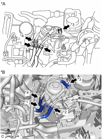
*A w/o Glow Plug Controller *B w/ Glow Plug Controller *1 No. 1 Fuel Hose *2 No. 2 Fuel Hose *3 No. 3 Fuel Hose *4 No. 4 Fuel Hose Slide the clip and disconnect the No. 3 fuel hose from the fuel filter assembly.
-
Slide the clip and disconnect the No. 2 fuel hose from the fuel filter assembly.
-
Slide the clip and disconnect the No. 1 fuel hose from the fuel filter assembly.
-
Slide the clip and disconnect the No. 4 fuel hose from the fuel filter assembly.
-
-
Disconnect the 5 fuel hoses. (w/ Combustion Type Power Heater)
-
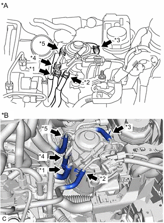
*A w/o Glow Plug Controller *B w/ Glow Plug Controller *1 No. 1 Fuel Hose *2 No. 2 Fuel Hose *3 No. 3 Fuel Hose *4 No. 4 Fuel Hose *5 Heater Fuel Hose Slide the clip and disconnect the No. 3 fuel hose from the fuel filter assembly.
-
Slide the clip and disconnect the No. 2 fuel hose from the fuel filter assembly.
-
Slide the clip and disconnect the No. 1 fuel hose from the fuel filter assembly.
-
Slide the clip and disconnect the No. 4 fuel hose from the fuel filter assembly.
-
Slide the clip and disconnect the heater fuel hose from the fuel filter assembly.
-
-
Remove the fuel filter assembly.
-
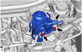
Disconnect the level warning switch connector.
-
Remove the 2 nuts and fuel filter assembly.
-
-
-
DRAIN FUEL
-
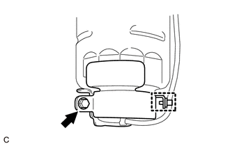
Loosen the drain bolt, and drain the fuel from the fuel filter assembly.
-
-
REMOVE FUEL FILTER GASKET
-
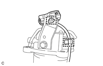
Disengage the 2 clamps to disconnect the wire harness from the fuel filter cap assembly.
-
Disengage the clamp and remove the bolt, nut, fuel filter cover and fuel filter gasket from the fuel filter assembly.
-
-
REMOVE LEVEL WARNING SWITCH
-
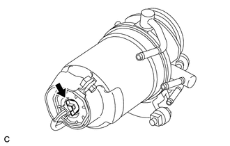
REMOVE FUEL FILTER ELEMENT SUB-ASSEMBLY
-
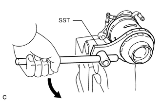
Using SST, remove the fuel filter element sub-assembly.
- SST
- 09228-64010
Note
Be careful not to damage the fuel filter cap assembly.
-
-
INSTALL FUEL FILTER ELEMENT SUB-ASSEMBLY
-
Check and clean the installation surface of the fuel filter element sub-assembly.
-
Apply a light coat of fuel to the gasket of a new fuel filter element sub-assembly.
-
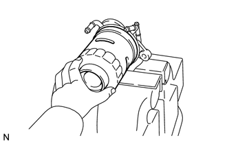
Temporarily install the fuel filter element sub-assembly, and tighten it until the gasket comes into contact with the seat.
-
Tighten the fuel filter element sub-assembly an additional 3/4 turn by hand.
-
-
INSTALL LEVEL WARNING SWITCH
-
INSTALL FUEL FILTER GASKET
-
Engage the clamp and install the fuel filter gasket and fuel filter cover to the fuel filter assembly with the bolt and nut.
- Torque:
- 3.4 N*m { 35 kgf*cm, 30 in.*lbf }
-
Engage the 2 clamps to connect the wire harness to the fuel filter cap assembly.
-
-
INSTALL FUEL FILTER ASSEMBLY
-
Install the fuel filter assembly.
-
Install the fuel filter assembly with the 2 nuts.
- Torque:
- 17 N*m { 173 kgf*cm, 13 ft.*lbf }
-
Connect the level warning switch connector.
-
-
Connect the 4 fuel hoses. (w/o Combustion Type Power Heater)
-
Connect the No. 1 fuel hose, No. 2 fuel hose and No. 3 fuel hose to the fuel filter assembly, and slide the 3 clips to secure them.
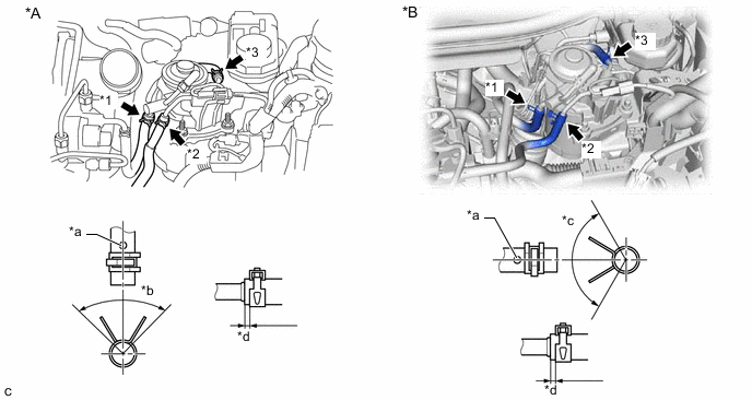
*A w/o Glow Plug Controller *B w/ Glow Plug Controller *1 No. 1 Fuel Hose *2 No. 2 Fuel Hose *3 No. 3 Fuel Hose - - *a Mark *b 90° *c 120° *d 1 to 5 mm (0.0394 to 0.197 in.) Note
-
Align the mark and connect each fuel hose.
-
Align the tabs of the clip with the fuel hose mark as shown in the illustration.
-
Position the clip so that the distance from the end of the fuel hose is 1 to 5 mm (0.0394 to 0.197 in.).
-
-
Connect the No. 4 fuel hose to the fuel filter assembly and slide the clip to secure it.
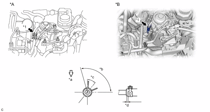
*A w/o Glow Plug Controller *B w/ Glow Plug Controller *1 No. 4 Fuel Hose - - *a Front of Vehicle *b 105° (Clip Area) *c 35° *d 1 to 5 mm (0.0394 to 0.197 in.) Tech Tips
Engage the clip within the area shown in the illustration.
-
-
Connect the 5 fuel hoses. (w/ Combustion Type Power Heater)
-
Connect the No. 1 fuel hose, No. 2 fuel hose, No. 3 fuel hose and heater fuel hose to the fuel filter assembly, and slide the 4 clips to secure them.
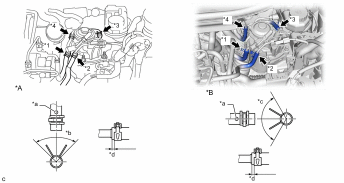
*A w/o Glow Plug Controller *B w/ Glow Plug Controller *1 No. 1 Fuel Hose *2 No. 2 Fuel Hose *3 No. 3 Fuel Hose *4 Heater Fuel Hose *a Mark *b 90° *c 120° *d 1 to 5 mm (0.0394 to 0.197 in.) Note
-
Align the mark and connect each fuel hose.
-
Align the tabs of the clip with the fuel hose mark as shown in the illustration.
-
Position the clip so that the distance from the end of the fuel hose is 1 to 5 mm (0.0394 to 0.197 in.).
-
-
Connect the No. 4 fuel hose to the fuel filter assembly and slide the clip to secure it.
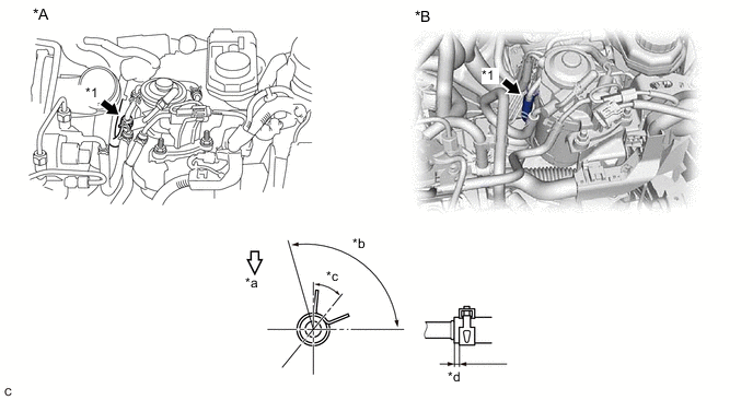
*A w/o Glow Plug Controller *B w/ Glow Plug Controller *1 No. 4 Fuel Hose - - *a Front of Vehicle *b 105° (Clip Area) *c 35° *d 1 to 5 mm (0.0394 to 0.197 in.) Tech Tips
Engage the clip within the area shown in the illustration.
-
-
-
INSTALL AIR CLEANER CASE SUB-ASSEMBLY
-
w/ Glow Plug Controller:
-
w/o Glow Plug Controller:
-
-
INSTALL AIR CLEANER CAP SUB-ASSEMBLY
-
w/ Glow Plug Controller:
-
w/o Glow Plug Controller:
-
-
BLEED AIR FROM FUEL SYSTEM
-
INSPECT FOR FUEL LEAK
-
w/ Glow Plug Controller:
-
w/o Glow Plug Controller:
-
-
INSTALL NO. 1 ENGINE COVER (w/ No. 1 Engine Cover)
-
w/ Glow Plug Controller:
-
w/o Glow Plug Controller:
-