ENGINE UNIT(w/o Glow Plug Controller) REASSEMBLY

PROCEDURE
-
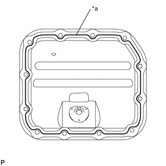
INSTALL OIL PAN SUB-ASSEMBLY
-
Apply seal packing to the oil pan sub-assembly in a continuous line as shown in the illustration.
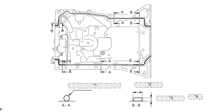
*1 φ 2.0 to 3.0 (0.0787 to 0.118) *2 Min. 7.0 (0.276) *3 Min. 3.0 (0.118) *4 mm (in.) Standard Seal Packing Diameter Area Bead Size
mm (in.)
A - A 2.0 to 3.0
(0.0787 to 0.118)
B - B Min. Width: 7.0 (0.276)
Min. Height: 3.0 (0.118)
Seal packing Toyota Genuine Seal Packing Black, Three Bond 1207B or equivalent Note
-
Remove any oil from the contact surfaces.
-
Install the oil pan within 3 minutes, and tighten the bolts within 15 minutes of applying the seal packing.
-
Do not start the engine for at least 2 hours after installing the oil pan sub-assembly.
-
-
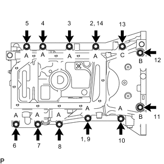
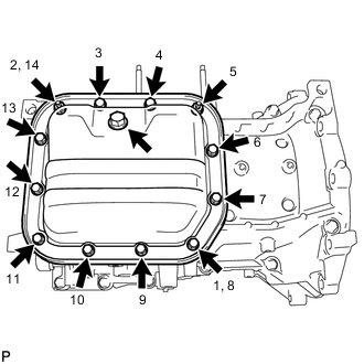
Using several steps, temporarily tighten the 12 bolts, and then tighten them to the specified torque in the order shown in the illustration.
- Torque:
- 21 N*m { 214 kgf*cm, 15 ft.*lbf }
Bolt Length Bolt Length
mm (in.)
A 35 (1.378) B 143.7 (5.657) C 119 (4.685)
-
-
INSTALL ENGINE REAR OIL SEAL
-
INSTALL ENGINE OIL LEVEL SENSOR
-
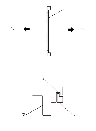
*1 Gasket *2 Engine Oil level Sensor *a Engine Oil level Sensor Side *b Float Side *c Groove Install a new gasket to the engine oil level sensor.
Note
Securely install the gasket to the engine oil level sensor groove.
-
Temporarily tighten the engine oil level sensor with the 5 bolts.
Note
Do not deform the engine oil level sensor float or allow it to come in contact with other parts.
-
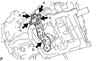
Fully tighten the 4 bolts (A) first, and then the bolt (B).
- Torque:
- 11 N*m { 112 kgf*cm, 8 ft.*lbf }
-
-
INSTALL NO. 2 OIL PAN SUB-ASSEMBLY
-
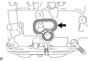
*a Seal Packing Apply seal packing (diameter 2.5 to 3.5 mm (0.0984 to 0.138 in.)) to the No. 2 oil pan sub-assembly in a continuous line as shown in the illustration.
Seal packing Toyota Genuine Seal Packing Black, Three Bond 1207B or equivalent Note
-
Remove any oil from the contact surfaces.
-
Install the No. 2 oil pan sub-assembly within 3 minutes, and tighten the bolts within 10 minutes of applying the seal packing.
-
Do not start the engine for at least 2 hours after installing the No. 2 oil pan sub-assembly.
-
-
Temporarily tighten the No. 2 oil pan sub-assembly with the 10 bolts and 2 nuts.
-
Fully tighten the 10 bolts and 2 nuts, as shown in the illustration.
- Torque:
- 9.0 N*m { 92 kgf*cm, 80 in.*lbf }
-
Install a new gasket and oil pan drain plug.
- Torque:
- 38 N*m { 387 kgf*cm, 28 ft.*lbf }
-
-
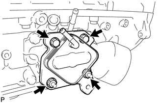
INSTALL OIL FILTER BRACKET SUB-ASSEMBLY
-
Check and clean the oil filter bracket sub-assembly installation surface.
-
Install a new gasket to the oil pan sub-assembly.
-
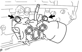
Install the oil filter bracket sub-assembly with the 2 bolts.
- Torque:
- 21 N*m { 214 kgf*cm, 15 ft.*lbf }
-
-
INSTALL OIL COOLER ASSEMBLY
-
Check and clean the oil cooler assembly installation surface.
-
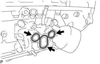
Install 2 new O-rings and a new gasket to the oil filter bracket sub-assembly.
-
Install the oil cooler assembly with the 2 bolts and 2 nuts.
- Torque:
- 21 N*m { 214 kgf*cm, 15 ft.*lbf }
-
-
INSTALL OIL FILTER ELEMENT
-
INSTALL CYLINDER BLOCK WATER JACKET SPACER
-
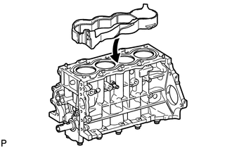
Install the cylinder block water jacket spacer to the cylinder block sub-assembly.
-
-
INSTALL CYLINDER HEAD GASKET
-
INSTALL CYLINDER HEAD SUB-ASSEMBLY
-
Apply a light coat of engine oil to the threads of the 10 cylinder head set bolts.
-
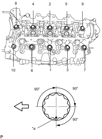
*a Paint Mark 
Front Using several steps, install and uniformly tighten the 10 cylinder head set bolts and 10 plate washers in the order shown in the illustration. (*1)
- Torque:
- 50 N*m { 510 kgf*cm, 37 ft.*lbf }
-
Mark the front of the 10 cylinder head set bolts with paint.
-
Using the same order as step (*1), tighten the 10 cylinder head set bolts an additional 90°.
-
Repeat the step above 2 more times as shown in the illustration.
-
Check that each paint mark is now 270° from the front.
-
-
INSTALL NO. 1 VALVE ROCKER ARM SUB-ASSEMBLY
-
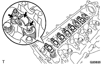
Apply engine oil to the valve stem end caps, No. 1 valve rocker arm sub-assembly pivot top surfaces and No. 1 valve rocker arm sub-assembly roller portions.
-
Install the 8 No. 1 valve rocker arm sub-assemblies.
-
-
INSTALL CAMSHAFT
-
INSTALL CHAIN DAMPER SPRING
-
Install the chain damper spring to the chain tensioner plate.
-
-
INSTALL NO. 2 CHAIN SUB-ASSEMBLY
-
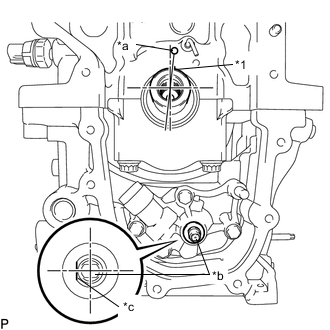
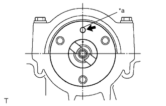
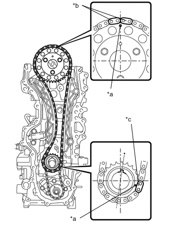
*1 Key *a TDC Mark *b Oil Pump Shaft *c Flat Side Align the crankshaft key with the TDC mark on the cylinder block sub-assembly.
-
Rotate the oil pump shaft so that the flat side faces left when viewing the cylinder block sub-assembly from the front.
-
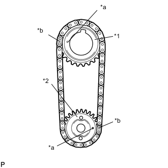
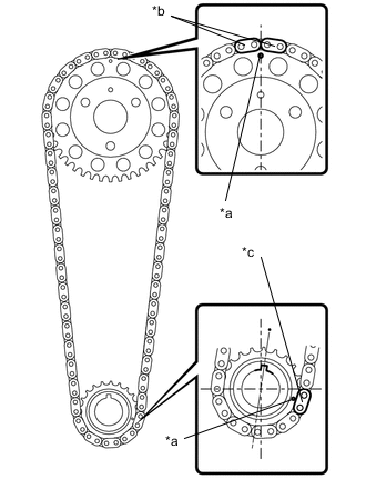
*1 Oil Pump Drive Gear *2 Oil Pump Drive Shaft Gear *a Timing Mark *b Orange Mark Plate Align the orange mark plates with the timing mark of each gear as shown in the illustration.
-
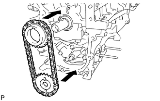
Install the sprockets onto the crankshaft and oil pump shaft with the No. 2 chain sub-assembly wrapped around the gears.
-
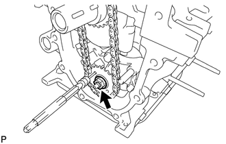
Insert a 4 mm (0.157 in.) diameter bar into the adjusting hole of the oil pump drive shaft gear to lock the gear in position, and then tighten the nut.
- Torque:
- 30 N*m { 306 kgf*cm, 22 ft.*lbf }
-
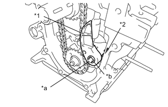
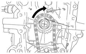
*1 Chain Tensioner Plate *2 Chain Damper Spring *a Pin *b Pivot Hole Install the chain tensioner plate with the chain damper spring to the pin.
Note
-
Push the chain tensioner plate so that the area around the pivot hole reaches the base of the pin.
-
The end of the chain damper spring should contact the side of the oil pan sub-assembly so that tension is applied to the No. 2 chain sub-assembly.
-
-
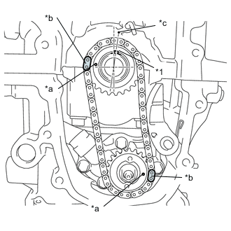
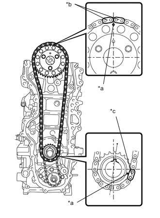
*1 Key *a Timing Mark *b Mark Plate *c TDC Mark Check that the mark plates and timing marks are in the positions shown in the illustration.
-
-
INSTALL CHAIN SUB-ASSEMBLY
-
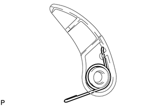
*a Straight Pin Turn the camshaft to set the straight pin in the position shown in the illustration.
-
*1 Key *a Turn *b TDC Mark Turn the crankshaft to set the key in the position shown in the illustration.
-
*a Timing Mark *b Orange Mark Plate *c Yellow Mark Plate Align the 2 orange mark plates with the timing mark on the camshaft timing sprocket, and the yellow mark plate with the timing mark on the crankshaft timing sprocket.
-
*a Timing Mark *b Orange Mark Plate *c Yellow Mark Plate Install the chain sub-assembly, camshaft timing sprocket and crankshaft timing sprocket together onto the engine.
-
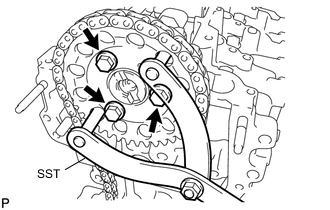
w/o Stop And Start System
-
Using SST, secure the camshaft timing sprocket, and install the camshaft timing sprocket with the 3 bolts.
- SST
- 09960-10010 ( 09962-01000, 09963-01000 )
- Torque:
- 20 N*m { 204 kgf*cm, 15 ft.*lbf }
-
-
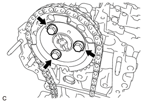
w/ Stop And Start System
-
Install the 3 bolts while holding the hexagonal portion of the camshaft, and then install the camshaft timing sprocket and sensor plate.
- Torque:
- 20 N*m { 204 kgf*cm, 15 ft.*lbf }
-
-
-
INSTALL NO. 1 CHAIN VIBRATION DAMPER
-
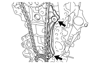
Install the No. 1 chain vibration damper with the 2 bolts.
- Torque:
- 21 N*m { 214 kgf*cm, 15 ft.*lbf }
-
-
INSTALL CHAIN TENSIONER SLIPPER
-
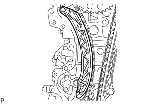
Install the chain tensioner slipper to the cylinder block sub-assembly.
-
-
INSTALL NO. 1 CHAIN TENSIONER ASSEMBLY
-
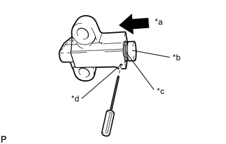
*a Push *b Plunger *c Groove *d Hole Push in the plunger until the groove is aligned with the hole, and then insert a 1.1 mm (0.0433 in.) diameter bar.
-
Install the No. 1 chain tensioner assembly with the 2 bolts.
- Torque:
- 21 N*m { 214 kgf*cm, 15 ft.*lbf }
-
Remove the 1.1 mm (0.0433 in.) diameter bar from the No. 1 chain tensioner assembly.
-
*a Timing Mark *b Orange Mark Plate *c Yellow Mark Plate Check that the mark plates and timing marks are in the positions shown in the illustration.
-
-
INSTALL INLET WATER HOUSING
-
Install a new No. 2 water inlet housing gasket to the inlet water housing.
-
Install the inlet water housing to the timing chain cover sub-assembly with the 3 bolts.
- Torque:
- 9.0 N*m { 92 kgf*cm, 80 in.*lbf }
-
-
INSTALL OIL CHECK VALVE SUB-ASSEMBLY
-
Using a 6 mm hexagon socket wrench, install the oil check valve sub-assembly with the bolt.
- Torque:
- 9.0 N*m { 92 kgf*cm, 80 in.*lbf }
-
-
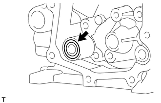
INSTALL TIMING CHAIN COVER OIL SEAL
-
Apply MP grease to a new timing chain cover oil seal lip.
Note
Keep the lip free from foreign matter.
-
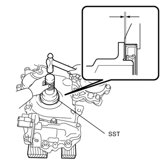
Using SST and a hammer, tap in the new timing chain cover oil seal until its surface is flush with the timing chain cover sub-assembly edge.
- SST
- 09223-22010
Oil seal tap in depth -1.0 to 0 mm (-0.0394 to 0 in.) Note
-
Do not tap in the timing chain cover oil seal at an angle.
-
Wipe off extra grease from the crankshaft.
-
-
INSTALL TIMING CHAIN COVER SUB-ASSEMBLY
-
Install the new oil pump gasket.
-
Apply seal packing to the engine body and oil pump as shown in the illustration below.
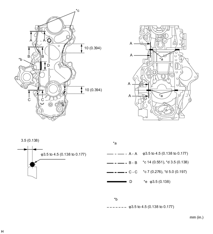
*a Seal Width (Toyota Genuine Seal Packing Black, Three Bond 1207B) *b Seal Width (Toyota Genuine Seal Packing 1282B, Three Bond 1282B) *c Width *d Height *e Double Line Area - - Note
-
Remove any oil from the contact surfaces.
-
Install the timing chain cover sub-assembly within 3 minutes, and tighten the bolts within 15 minutes of applying the seal packing.
-
Do not start the engine for at least 2 hours after installing the timing chain cover sub-assembly.
Seal packing Engine water pump assembly: Toyota Genuine Seal Packing 1282B, Three Bond 1282B or equivalent Other: Toyota Genuine Seal Packing Black, Three Bond 1207B or equivalent -
-
Install the timing chain cover sub-assembly with the 20 bolts and 2 nuts, as shown in the illustration.
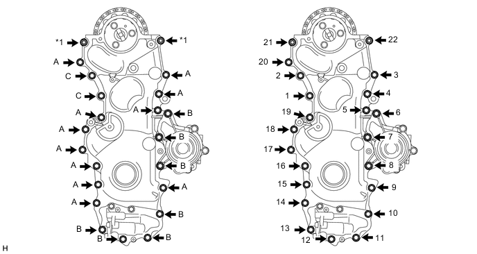
*1 Nut - - - Torque:
- Bolt A, B, Nut
- 21 N*m { 214 kgf*cm, 15 ft.*lbf }
- Bolt C
- 40 N*m { 408 kgf*cm, 30 ft.*lbf }
Bolt Length Bolt Length
mm (in.)
A 25 (0.984) B 35 (1.378) C 40 (1.575) Note
-
Make sure that the chain sub-assembly and No. 2 chain sub-assembly do not come into contact with the seal packing when installing the timing chain cover sub-assembly.
-
Install the engine mounting bracket RH within 10 minutes of installing the timing chain cover sub-assembly.
-
-
INSTALL CRANKSHAFT DAMPER SUB-ASSEMBLY
-
INSTALL OIL PRESSURE SWITCHING VALVE ASSEMBLY
-
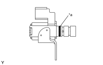
*a O-ring Apply a light coat of engine oil to the O-ring of the oil pressure switching valve assembly.
-
Install the oil pressure switching valve assembly with the bolt.
- Torque:
- 9.0 N*m { 92 kgf*cm, 80 in.*lbf }
Note
Make sure that the O-ring is not torn or pinched when installing.
-
-
INSTALL NO. 2 TIMING CHAIN COVER
-
Install the No. 2 timing chain cover with the harness bracket and bolt.
- Torque:
- 9.0 N*m { 92 kgf*cm, 80 in.*lbf }
-
-
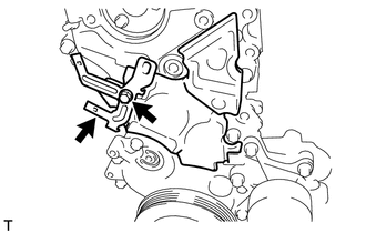
INSTALL ENGINE MOUNTING BRACKET RH
-
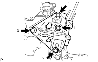
Temporarily tighten the engine mounting bracket RH with the 4 bolts.
-
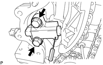
Fully tighten the 4 bolts, as shown in the illustration.
- Torque:
- 55 N*m { 561 kgf*cm, 41 ft.*lbf }
-
-
INSTALL OIL PRESSURE SENDER GAGE ASSEMBLY
-
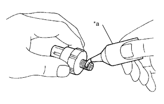
*a Adhesive Apply adhesive to 2 or 3 threads of the oil pressure sender gage assembly.
Adhesive Toyota Genuine Adhesive 1344, Three Bond 1344 or equivalent -
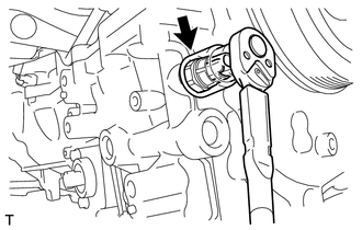
Using a 27 mm deep socket wrench, install the oil pressure sender gage assembly.
- Torque:
- 15 N*m { 153 kgf*cm, 11 ft.*lbf }
-
-
INSTALL WATER INLET
-
Install a new No. 1 water inlet housing gasket to the water inlet.
-
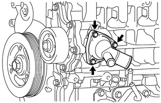
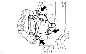
Install the water inlet with the 3 bolts.
- Torque:
- 9.0 N*m { 92 kgf*cm, 80 in.*lbf }
-
-
INSTALL OUTLET WATER SUB-ASSEMBLY
-
Install a new water outlet gasket to the cylinder head sub-assembly.
-
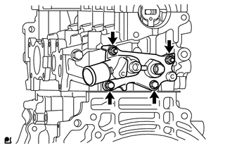
Install the outlet water sub-assembly with the 2 bolts and 2 nuts.
- Torque:
- 11 N*m { 112 kgf*cm, 8 ft.*lbf }
-
-
INSTALL WATER TEMPERATURE SENSOR
-
Install a new gasket to the water temperature sensor.
-
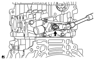
Using a 19 mm deep socket wrench, install the water temperature sensor.
- Torque:
- 19.6 N*m { 200 kgf*cm, 14 ft.*lbf }
-
-
CHECK VALVE CLEARANCE
-
ADJUST VALVE CLEARANCE
-
INSTALL CYLINDER HEAD COVER SUB-ASSEMBLY
-
Install the cylinder head gasket to the cylinder head cover sub-assembly.
-
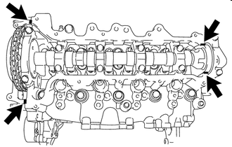

Seal Packing Apply seal packing to the 4 locations shown in the illustration, and then install the cylinder head cover sub-assembly.
Seal packing Toyota Genuine Seal Packing Black, Three Bond 1207B or equivalent Note
-
Remove any oil from the contact surfaces.
-
Install the cylinder head cover sub-assembly within 3 minutes, and tighten the bolts within 15 minutes of applying the seal packing.
-
Do not start the engine for at least 2 hours after installing the cylinder head cover sub-assembly.
-
-
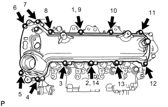
Temporarily tighten the cylinder head cover sub-assembly with the 12 bolts.
-
Fully tighten the 12 bolts in the order shown in the illustration.
- Torque:
- 11 N*m { 112 kgf*cm, 8 ft.*lbf }
-
-
INSTALL OIL FILLER CAP SUB-ASSEMBLY
-
Install the oil filler cap gasket to the oil filler cap sub-assembly.
-
Install the oil filler cap sub-assembly to the cylinder head cover sub-assembly.
-