ENGINE UNIT(w/ Glow Plug Controller) DISASSEMBLY

PROCEDURE
-
REMOVE ENGINE COOLANT TEMPERATURE SENSOR
-
REMOVE WATER OUTLET SUB-ASSEMBLY
-
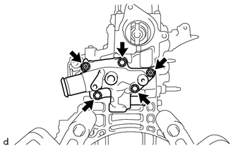
Remove the 3 bolts, 2 nuts and water outlet sub-assembly from the cylinder head sub-assembly.
-
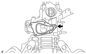
Remove the water outlet gasket from the cylinder head sub-assembly.
-
-
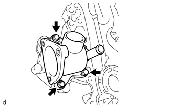
REMOVE WATER INLET
-
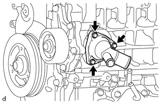
Remove the 3 bolts and water inlet from the water inlet housing.
-
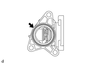
Remove the No. 1 water inlet housing gasket from the water inlet.
-
-
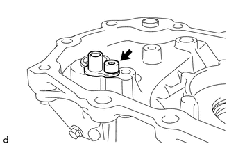
REMOVE OIL PRESSURE SENDER GAGE ASSEMBLY
-
REMOVE OIL FILLER CAP SUB-ASSEMBLY
-
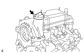
Remove the oil filler cap sub-assembly from the cylinder head cover sub-assembly.
-
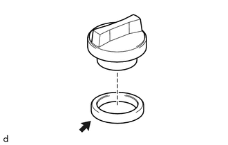
Remove the oil filler cap gasket from the oil filler cap sub-assembly.
-
-
REMOVE CYLINDER HEAD COVER SUB-ASSEMBLY
-
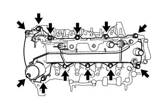
Remove the 11 bolts, nut and cylinder head cover sub-assembly from the cylinder head sub-assembly.
-
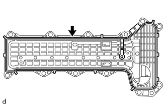
Remove the cylinder head cover gasket from the cylinder head cover sub-assembly.
-
-
REMOVE ENGINE MOUNTING BRACKET RH
-
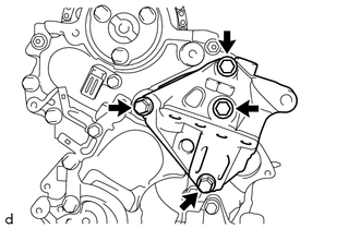
Remove the 4 bolts and engine mounting bracket RH from the timing chain cover sub-assembly.
-
-
REMOVE NO. 2 TIMING CHAIN COVER
-
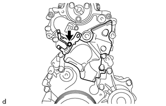
Remove the bolt and manifold temperature sensor bracket from the timing chain cover sub-assembly.
-
Remove the No. 2 timing chain cover from the timing chain cover sub-assembly.
-
-
REMOVE CAMSHAFT POSITION SENSOR
-
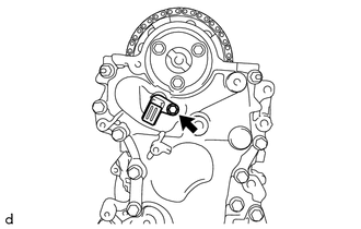
Remove the bolt and camshaft position sensor from the timing chain cover sub-assembly.
Note
If a component has been dropped or subjected to a strong impact, replace the camshaft position sensor.
-
-
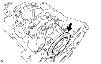
REMOVE CRANKSHAFT DAMPER SUB-ASSEMBLY
-
REMOVE TIMING CHAIN COVER SUB-ASSEMBLY
-
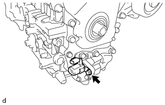
Remove the bolt and oil pressure switching valve assembly from the timing chain cover sub-assembly.
Note
If a component has been dropped or subjected to a strong impact, replace the oil pressure switching valve assembly.
-
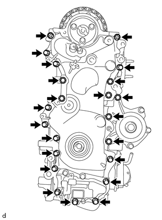
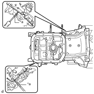
Remove the 20 bolts and 2 nuts.
-
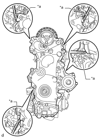
*a Protective Tape Using a screwdriver with its tip wrapped in protective tape, remove the timing chain cover sub-assembly by prying between the cylinder head sub-assembly and cylinder block sub-assembly.
Note
Do not damage the contact surfaces of the timing chain cover sub-assembly, cylinder head sub-assembly and cylinder block sub-assembly.
-
Remove the oil pump gasket from the oil pan sub-assembly.
-
-
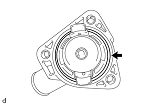
REMOVE TIMING CHAIN COVER OIL SEAL
-
*a Protective Tape Using a screwdriver with its tip wrapped in protective tape, remove the timing chain cover oil seal from the timing chain cover sub-assembly.
-
-
REMOVE OIL CHECK VALVE SUB-ASSEMBLY
-
Using a 5 mm hexagon wrench, remove the bolt and oil check valve sub-assembly from the timing chain cover sub-assembly.
-
-
REMOVE WATER INLET HOUSING
-
Remove the 3 bolts and water inlet housing from the timing chain cover sub-assembly.
-
Remove the No. 2 water inlet housing gasket from the inlet water housing.
-
-
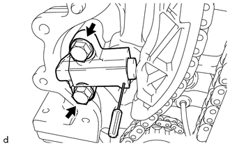
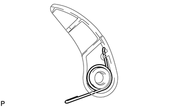
REMOVE NO. 1 CHAIN TENSIONER ASSEMBLY
Note
Do not rotate the crankshaft with the No. 1 chain tensioner assembly removed.
-
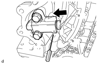
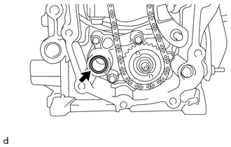
*a Plunger *b Groove *c Hole 
Push Push in the plunger until the groove is aligned with the hole, and then insert a 1.1 mm (0.0433 in.) diameter bar.
-
Remove the 2 bolts and No. 1 chain tensioner assembly from the cylinder block sub-assembly.
-
-
REMOVE CHAIN TENSIONER SLIPPER
-
Remove the chain tensioner slipper from the cylinder head sub-assembly.
-
-
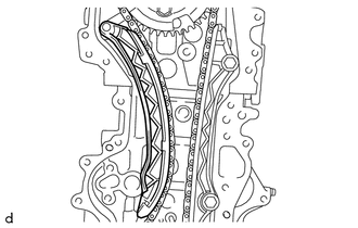
REMOVE NO. 1 CHAIN VIBRATION DAMPER
-
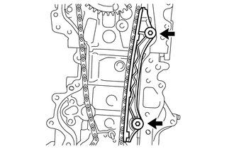
Using an 8 mm socket hexagon wrench, remove the 2 bolts and No. 1 chain vibration damper from the cylinder head sub-assembly and cylinder block sub-assembly.
-
-
REMOVE CHAIN SUB-ASSEMBLY
-
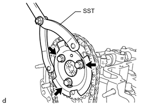
Using SST, hold the camshaft timing sprocket.
- SST
- 09960-10010 ( 09962-01000, 09963-01000 )
-
Remove the 3 bolts and sensor plate.
-
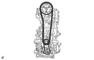
Remove the camshaft timing sprocket, crankshaft timing sprocket and chain sub-assembly together.
-
-
REMOVE NO. 2 CHAIN SUB-ASSEMBLY
-
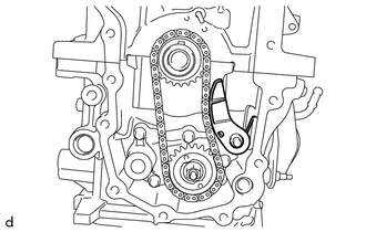
Remove the chain tensioner plate with the chain damper spring from the pin.
-
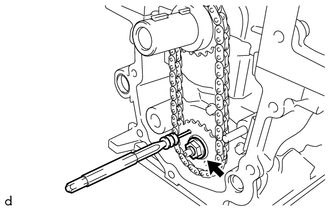
Insert a 4 mm (0.157 in.) diameter bar into the adjusting hole of the oil pump drive shaft gear to lock the gear in position, and then remove the nut.
-
Remove the oil pump drive gear, oil pump drive shaft gear and No. 2 chain sub-assembly together.
-
-
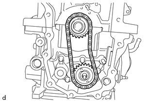
REMOVE CHAIN DAMPER SPRING
-
Remove the chain damper spring from the chain tensioner plate.
-
-
REMOVE CAMSHAFT
-
REMOVE NO. 1 VALVE ROCKER ARM SUB-ASSEMBLY
-
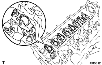
Remove the 8 No. 1 valve rocker arm sub-assemblies from the cylinder head sub-assembly.
-
-
REMOVE CYLINDER HEAD SUB-ASSEMBLY
-
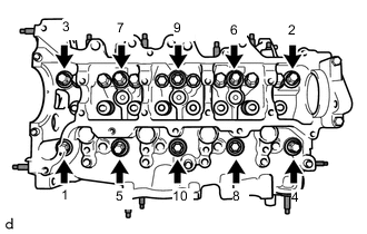
Loosen and remove the 10 cylinder head set bolts and 10 cylinder head set plate washers in several steps in the order shown in the illustration.
Note
-
When removing the cylinder head set bolts, do not drop the plate washers into the engine.
-
Removing the cylinder head set bolts in the wrong order may cause damage to the cylinder head sub-assembly.
-
-
Remove the cylinder head sub-assembly from the cylinder block sub-assembly.
-
-
REMOVE CYLINDER HEAD GASKET
-
REMOVE CYLINDER BLOCK WATER JACKET SPACER
-
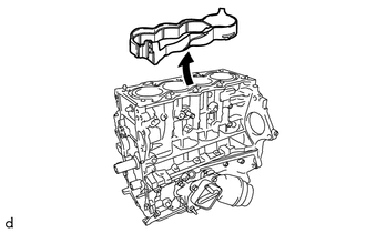
Remove the cylinder block water jacket spacer from the cylinder block sub-assembly.
-
-
REMOVE OIL FILTER ELEMENT
-
REMOVE OIL COOLER ASSEMBLY
-
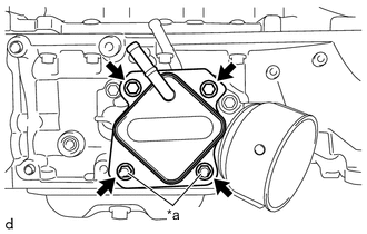
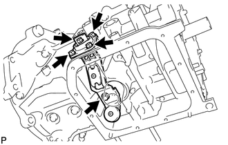
*a Nut and Plate Washer Remove the 2 bolts, 2 nuts, 2 plate washers and oil cooler assembly from the oil filter bracket sub-assembly.
-
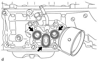
Remove the 2 O-rings and gasket from the oil filter bracket sub-assembly.
-
-
REMOVE OIL FILTER BRACKET SUB-ASSEMBLY
-
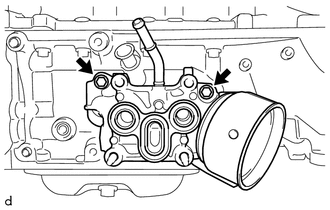
Remove the 2 bolts and oil filter bracket sub-assembly from the oil pan sub-assembly.
-
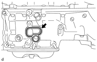
Remove the oil filter bracket gasket from the oil pan sub-assembly.
-
-
REMOVE NO. 2 OIL PAN SUB-ASSEMBLY
-
Remove the oil pan drain plug and oil pan drain plug gasket from the No. 2 oil pan sub-assembly.
-
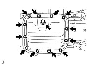
Remove the 10 bolts and 2 nuts.
-
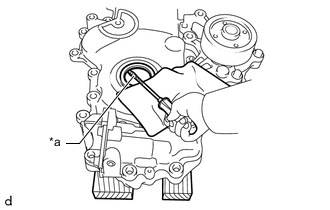
*a Oil Pan Seal Cutter Insert the oil pan seal cutter blade between the oil pan sub-assembly and No. 2 oil pan sub-assembly, and cut off the applied sealer.
Note
Do not damage the oil pan sub-assembly or No. 2 oil pan sub-assembly.
-
Remove the No. 2 oil pan sub-assembly from the oil pan sub-assembly.
-
-
REMOVE ENGINE OIL LEVEL SENSOR
-
Remove the 5 bolts and engine oil level sensor from the oil pan sub-assembly.
-
-
REMOVE OIL PAN SUB-ASSEMBLY
-
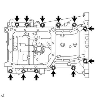
Remove the 12 bolts.
-
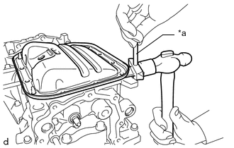
*a Protective Tape Using a screwdriver with its tip wrapped in protective tape, remove the oil pan sub-assembly by prying between the cylinder block sub-assembly and oil pan sub-assembly.
Note
-
Do not apply excessive force when prying between the cylinder block sub-assembly and oil pan sub-assembly.
-
Do not damage the contact surface of the cylinder block sub-assembly and oil pan sub-assembly.
-
-
-
REMOVE ENGINE REAR OIL SEAL
-
Remove the engine rear oil seal from the crankshaft and cylinder block sub-assembly.
-