ENGINE ASSEMBLY(w/o Glow Plug Controller) REMOVAL
CAUTION / NOTICE / HINT
CAUTION:
Some of these service operations affect the multi-mode manual transaxle system. Read the precautionary notices concerning the multi-mode manual transaxle system before servicing.
Note
-
When the manual transaxle assembly or multi-mode manual transaxle assembly is removed, be sure to use a new clutch release with bearing cylinder and new installation bolts. Removal of the manual transaxle assembly or multi-mode manual transaxle assembly allows the compressed clutch release with bearing cylinder to return to its original position, and dust could damage the seal of the clutch release with bearing cylinder, possibly causing clutch fluid leaks.
-
After replacing the engine assembly, perform both "Injector Compensation" and "Pilot Quantity Learning Values Reset" using the GTS.
PROCEDURE
-
PRECAUTION
Note
After turning the ignition switch off, waiting time may be required before disconnecting the cable from the negative (-) battery terminal. Therefore, make sure to read the disconnecting the cable from the negative (-) battery terminal notices before proceeding with work.
-
REGARDING PARTS REMOVAL (for Multi-Mode Manual Transaxle)
-
Before removing the clutch actuator or multi-mode manual transaxle assembly from the vehicle, perform the Active Test to set the clutch actuator to the "Clamp" position.
Note
If the actuator is not set to the "Clamp" position, the clutch fluid may spray.
Tech Tips
If the clutch actuator cannot be set to the "Clamp" position due to a malfunction (sticking, etc.), then release the clutch fluid pressure through the bleeder plug to prevent the clutch fluid from spraying.
-
-
DISCONNECT CABLE FROM NEGATIVE BATTERY TERMINAL
Note
When disconnecting the cable, some systems need to be initialized after the cable is reconnected.
-
ALIGN FRONT WHEELS FACING STRAIGHT AHEAD
-
REMOVE FRONT WHEELS
-
REMOVE FRONT LOWER BUMPER ABSORBER
-
Remove the 8 bolts, 4 screws and front lower bumper absorber.
-
-
REMOVE NO. 1 ENGINE UNDER COVER (for Half Cover Type)
-
Remove the 2 bolts, 7 clips and No. 1 engine under cover.
-
-
REMOVE NO. 1 ENGINE UNDER COVER (for Full Cover Type)
-
Remove the 2 bolts, 11 clips and No. 1 engine under cover.
-
-
REMOVE CENTER NO. 4 ENGINE UNDER COVER (for Half Cover Type)
-
Remove the 5 clips and center No. 4 engine under cover.
-
-
REMOVE CENTER NO. 4 ENGINE UNDER COVER (for Full Cover Type)
-
Remove the 2 clips and center No. 4 engine under cover.
-
-
REMOVE FRONT NO. 3 ENGINE UNDER COVER (for Full Cover Type)
-
Remove the 4 clips and front No. 3 engine under cover.
-
-
REMOVE REAR ENGINE UNDER COVER LH
-
Remove the 5 clips and rear engine under cover LH.
-
-
REMOVE REAR ENGINE UNDER COVER RH
-
Remove the 5 clips and rear engine under cover RH.
-
-
DRAIN ENGINE OIL
-
DRAIN ENGINE COOLANT
-
DRAIN MANUAL TRANSAXLE OIL (for Manual Transaxle)
-
DRAIN MANUAL TRANSAXLE OIL (for Multi-Mode Manual Transaxle)
-
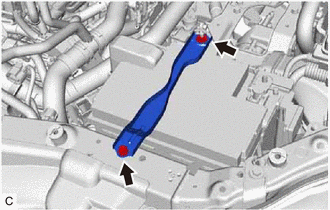
REMOVE NO. 1 ENGINE COVER (w/ No. 1 Engine Cover)
-
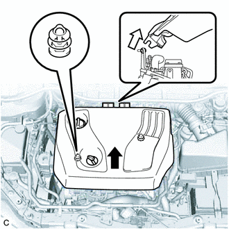

Disengage the 2 grommets first. 
Disengage the 2 hooks next. Lift the front of the No. 1 engine cover to disengage the 2 grommets from the 2 pins. Then disengage the 2 hooks from the No. 2 engine cover bracket, and remove the No. 1 engine cover.
-
-
REMOVE OUTER COWL TOP PANEL (for LHD)
-
REMOVE OUTER COWL TOP PANEL (for RHD)
-
REMOVE BATTERY
-
Loosen the nut, and separate the positive (+) battery terminal.
-
Remove the nut, bolt, battery clamp sub-assembly and battery clamp bolt.
-
Remove the battery.
-
Remove the battery tray.
-
-
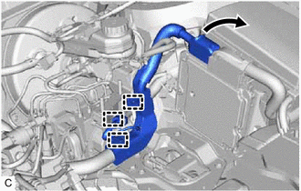
REMOVE AIR CLEANER CAP SUB-ASSEMBLY
-
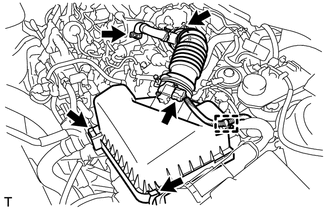
Disconnect the wire harness clamp, connector and ventilation hose.
-
Loosen the hose clamp.
-
Unlock the 2 lock clamps and remove the air cleaner cap sub-assembly.
-
-
REMOVE AIR CLEANER CASE SUB-ASSEMBLY
-
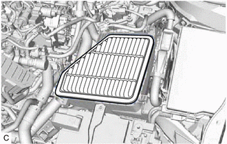
Remove the air cleaner filter element sub-assembly.
-
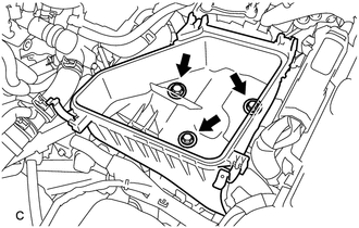
Remove the 3 bolts and air cleaner case sub-assembly.
-
-
REMOVE FUEL FILTER ASSEMBLY
-
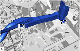
DISCONNECT WIRE HARNESS
-
Pull up the lever to disconnect the ECM connector.
-
Disconnect the 3 wire harness clamps from the fuel filter support.
-
Remove the No. 1 relay block cover from the engine room relay block and junction block assembly.
-
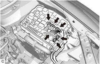
Remove the 2 nuts from the engine room relay block and junction block assembly.
-
Disconnect the 4 wire harness connectors, 2 claws and wire harness from the engine room relay block and junction block assembly.
-
Disconnect the 2 wire harness clamps.
-
Remove the bolt and disconnect the No. 3 engine wire from the manual transaxle assembly.
-
-
DISCONNECT WIRE HARNESS (for Multi-Mode Manual Transaxle)
-
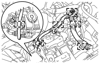
Disconnect the 6 wire harness clamps.
-
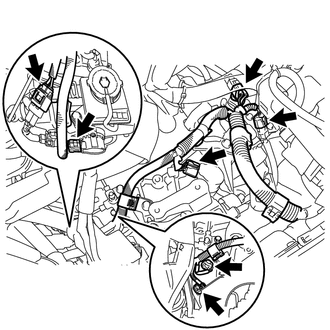
Disconnect the 7 connectors.
-
-
REMOVE GLOW PLUG RELAY ASSEMBLY
-
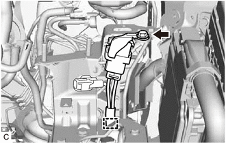
Remove the bolt and disconnect the glow plug relay assembly from the fuel filter support.
-
Disconnect the wire harness clamp from the fuel filter support.
-
-
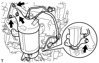
REMOVE FUEL FILTER SUPPORT
-
Disconnect the wire harness clamp from the fuel filter support.
-
Remove the 3 bolts and fuel filter support.
-
-
REMOVE AIR CLEANER BRACKET
-
Remove the 3 bolts and air cleaner bracket.
-
-
REMOVE NO. 2 BATTERY CARRIER
-
Remove the 4 bolts and No. 2 battery carrier.
-
-
REMOVE NO. 3 AIR HOSE
-
Loosen the 2 hose clamps and remove the No. 3 air hose.
-
-
REMOVE INTERCOOLER AIR HOSE
-
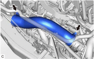
Loosen the 2 hose clamps and remove the intercooler air hose.
-
-
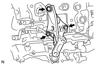
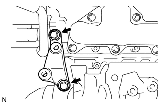
SEPARATE TRANSMISSION CONTROL CABLE ASSEMBLY (for Manual Transaxle)
-
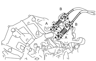
Remove the 2 clips (A) and disconnect the 2 transmission control cable assemblies from the manual transaxle assembly.
-
Remove the 2 clips (B) and disconnect the 2 transmission control cable assemblies from the control cable bracket assembly.
-
Remove the bolt and disconnect the transmission control cable assembly from the rear engine mounting bracket.
-
-
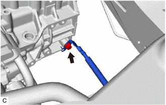
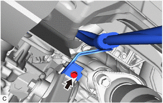
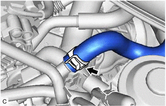
DISCONNECT UNION TO CONNECTOR TUBE HOSE
-
Slide the clip and disconnect the union to connector tube hose from the cylinder head cover sub-assembly.
-
-
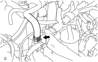
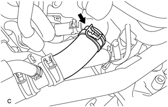
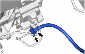
REMOVE WATER BY-PASS HOSE
-
Slide the clip and disconnect the water by-pass hose from the water inlet.
-
-
DISCONNECT NO. 2 RADIATOR HOSE
-
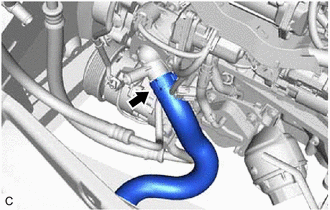
Slide the clip and disconnect the No. 2 radiator hose from the water inlet.
-
-
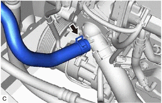
DISCONNECT NO. 1 RADIATOR HOSE
-
Slide the clip and disconnect the No. 1 radiator hose from the outlet water sub-assembly.
-
-
DISCONNECT INLET HEATER WATER HOSE A (w/o Combustion Type Power Heater)
-
Slide the clip and disconnect the inlet heater water hose A from the inlet heater water pipe A.
-
-
DISCONNECT INLET HEATER WATER HOSE D (w/ Combustion Type Power Heater)
-
Slide the clip and disconnect the inlet heater water hose D from the inlet heater water pipe A.
-
-
DISCONNECT OUTLET HEATER WATER HOSE
-
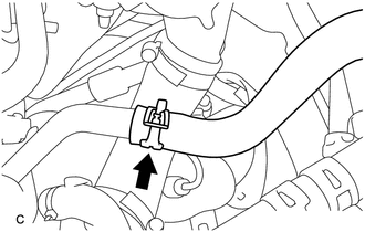
Slide the clip and disconnect the outlet heater water hose from the water by-pass pipe sub-assembly.
-
-
REMOVE V-RIBBED BELT
-
SEPARATE COMPRESSOR ASSEMBLY WITH PULLEY (w/ Air Conditioning System)
-
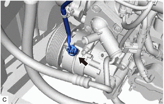
Disconnect the connector.
-
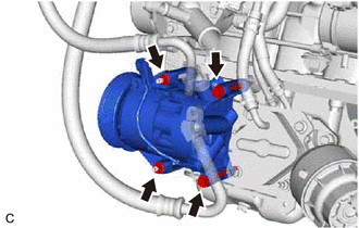
Remove the 2 bolts and 2 nuts.
-
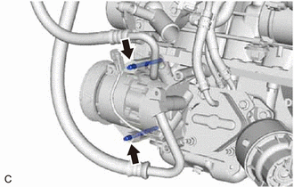
Using an E8 "TORX" socket wrench, remove the 2 stud bolts.
-
Separate the compressor assembly with pulley.
Tech Tips
It is not necessary to completely remove the compressor assembly with pulley. With the hoses connected to the compressor assembly with pulley, hang the compressor assembly with pulley on the vehicle body with a rope.
-
-
SECURE STEERING WHEEL
-
REMOVE COLUMN HOLE COVER SILENCER SHEET
-
SEPARATE NO. 2 STEERING INTERMEDIATE SHAFT ASSEMBLY
-
SEPARATE NO. 1 STEERING COLUMN HOLE COVER SUB-ASSEMBLY
-
REMOVE FRONT CENTER FLOOR BRACE SUB-ASSEMBLY
-
REMOVE FRONT EXHAUST PIPE ASSEMBLY
-
REMOVE FRONT DRIVE SHAFT ASSEMBLY LH
-
REMOVE FRONT DRIVE SHAFT ASSEMBLY RH
-
DISCONNECT NO. 1 CLUTCH HOSE (for Manual Transaxle)
-
Using a 10 mm union nut wrench, disconnect the No. 1 clutch hose from the accumulator to flexible hose tube.
-
Remove the clip and separate the No. 1 clutch hose from the flexible hose bracket.
-
-
REMOVE FRONT ENGINE MOUNTING BRACKET LOWER REINFORCEMENT (w/ Reinforcement)
-
REMOVE FRONT SUSPENSION MEMBER REINFORCEMENT LH
-
REMOVE FRONT SUSPENSION MEMBER REINFORCEMENT RH
Tech Tips
Perform the same procedure as for the LH side.
-
REMOVE FRONT SUSPENSION MEMBER REAR BRACE LH
-
REMOVE FRONT SUSPENSION MEMBER REAR BRACE RH
Tech Tips
Perform the same procedure as for the LH side.
-
REMOVE FRONT SUSPENSION CROSSMEMBER SUB-ASSEMBLY
-
REMOVE ENGINE ASSEMBLY WITH TRANSAXLE
-
Set an engine lifter.
Note
-
Place height adjustment attachments and plate lift attachments under the engine assembly with transaxle.
-
Do not position the height adjustment attachments or plate lift attachments under the front crossmember sub-assembly.
-
Do not perform any procedure while the engine assembly is suspended because doing so may cause the engine assembly to drop, resulting in injury. However, the engine assembly needs to be suspended when it is installed to or removed from an engine stand.
-
-
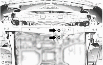
Remove the 2 bolts to separate the front engine mounting insulator from the front crossmember sub-assembly.
-
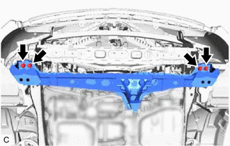
Remove the 4 bolts and front crossmember sub-assembly.
-
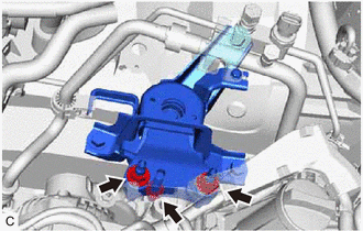
Remove the 3 nuts and separate the engine mounting insulator sub-assembly RH.
-
Remove the through bolt and nut, and separate the engine mounting insulator LH.
Tech Tips
When removing the through bolt, keep the nut from rotating.
-
Carefully remove the engine assembly with transaxle from the vehicle.
Note
Make sure that the engine assembly with transaxle is clear of all wiring and hoses.
-
-
INSTALL ENGINE HANGER
-
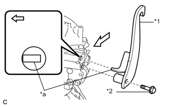
*1 No. 1 Engine Hanger (Part No. 12281-33050) *2 Bolt (Part No. 91552-81050) *a Tab Engine Rear Install the No. 1 engine hanger with a new bolt as shown in the illustration.
- Torque:
- 40 N*m { 408 kgf*cm, 30 ft.*lbf }
Note
-
Be sure to install the No. 1 engine hanger with the tab contacting the rear side of the hole.
-
Be sure to use a new bolt to install the No. 1 engine hanger.
-
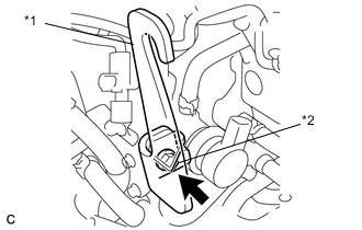
*1 No. 2 Engine Hanger (Part No. 12282-33022) *2 Bolt (Part No. 91672-81025) Install the No. 2 engine hanger with a new bolt as shown in the illustration.
- Torque:
- 50 N*m { 510 kgf*cm, 37 ft.*lbf }
Note
Be sure to use a new bolt to install the No. 2 engine hanger.
-
Using an engine sling device and a chain block, suspend the engine assembly with transaxle.
-
-
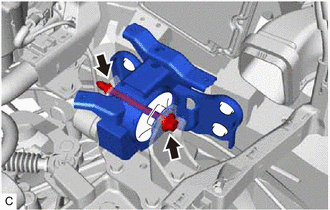
REMOVE FRONT ENGINE MOUNTING INSULATOR
-
Remove the through bolt, nut and front engine mounting insulator.
Tech Tips
When removing the through bolt, keep the nut from rotating.
-
-
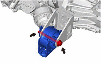
REMOVE REAR ENGINE MOUNTING INSULATOR
-
Remove the through bolt and rear engine mounting insulator.
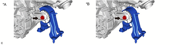
*A Type A *B Type B
-
-
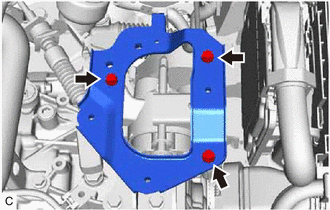
REMOVE ENGINE MOUNTING INSULATOR LH
Tech Tips
Perform this procedure only when replacement of the engine mounting insulator LH is necessary.
-
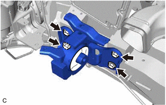
Remove the 4 bolts and engine mounting insulator LH.
-
-
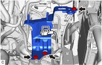
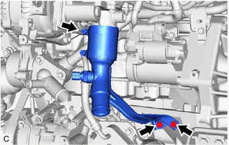
REMOVE ENGINE MOUNTING INSULATOR SUB-ASSEMBLY RH
Tech Tips
Perform this procedure only when replacement of the engine mounting insulator sub-assembly RH is necessary.
-
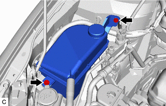
Remove the 2 bolts and separate the radiator reserve tank assembly.
-
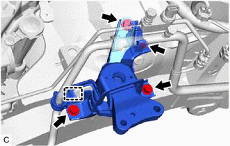
Remove the bolt and separate the cooler pipe clamp bracket from the engine mounting insulator sub-assembly RH.
-
Disconnect the cooler pipe clamp from the engine mounting insulator sub-assembly RH.
-
Remove the 3 bolts and engine mounting insulator sub-assembly RH.
-
-
REMOVE NO. 1 AIR TUBE
-
for EC69:
-
for EC65A:
-
-
REMOVE STARTER ASSEMBLY (w/o Stop And Start System)
-
REMOVE STARTER ASSEMBLY (w/ Stop And Start System)
-
DISCONNECT WIRE HARNESS (for Manual Transaxle)
-
w/o Stop And Start System:
-
w/ Stop And Start System:
-
-
DISCONNECT WIRE HARNESS (for Multi-Mode Manual Transaxle)
-
REMOVE MANUAL TRANSAXLE ASSEMBLY (for Manual Transaxle)
-
REMOVE MULTI-MODE MANUAL TRANSAXLE ASSEMBLY (for Multi-Mode Manual Transaxle)
-
REMOVE ACCUMULATOR TO FLEXIBLE HOSE TUBE (for Manual Transaxle)
-
REMOVE BLEEDER CLUTCH RELEASE TUBE (for Multi-Mode Manual Transaxle)
-
REMOVE CLUTCH RELEASE BLEEDER SUB-ASSEMBLY (for Manual Transaxle)
-
REMOVE CLUTCH RELEASE BLEEDER SUB-ASSEMBLY (for Multi-Mode Manual Transaxle)
-
REMOVE CLUTCH RELEASE WITH BEARING CYLINDER ASSEMBLY (for Manual Transaxle)
-
REMOVE CLUTCH RELEASE WITH BEARING CYLINDER ASSEMBLY (for Multi-Mode Manual Transaxle)
-
REMOVE CLUTCH RELEASE CYLINDER TO BLEEDER TUBE (for Manual Transaxle)
-
REMOVE CLUTCH RELEASE CYLINDER TO BLEEDER TUBE (for Multi-Mode Manual Transaxle)
-
REMOVE ENGINE WIRE
-
Disconnect all the wire harnesses and connectors. Make sure that no wire harnesses are connected to the engine.
-
-
REMOVE NO. 2 AIR TUBE
-
Loosen the hose clamp.
-
Remove the 2 bolts and No. 2 air tube.
-
-
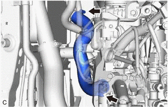
REMOVE OUTLET HEATER WATER HOSE A
-
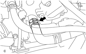
Slide the clip and remove the outlet heater water hose A from the outlet outer water sub-assembly.
-
-
REMOVE HARNESS BRACKET
-
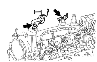
w/o No. 1 Engine Cover:
-
Remove the 2 nuts and 2 harness brackets.
-
-
w/ No. 1 Engine Cover:
-
Remove the 2 nuts, No. 2 engine cover bracket and 2 harness brackets.
-
-
-
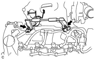
REMOVE SENSOR BRACKET
-
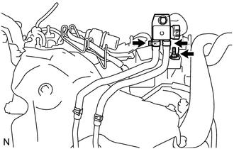
Slide the 2 clips and disconnect the 2 vacuum transmitting hoses.
-
Remove the nut and sensor bracket.
-
-
REMOVE NO. 1 TURBO INSULATOR
-
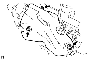
Remove the 3 bolts and No. 1 turbo insulator.
-
-
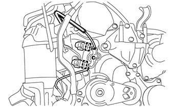
REMOVE NO. 2 VACUUM PIPE
-
REMOVE DRIVE SHAFT HEAT INSULATOR SUB-ASSEMBLY
-
REMOVE NO. 4 MANIFOLD SUPPORT BRACKET
-
REMOVE NO. 3 MANIFOLD SUPPORT BRACKET
-
REMOVE NO. 2 EXHAUST MANIFOLD CONVERTER SUB-ASSEMBLY
-
REMOVE EXHAUST MANIFOLD CONVERTER SUB-ASSEMBLY
-
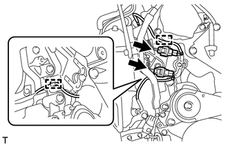
Disconnect the 2 exhaust gas temperature sensor connectors.
-
Disengage the 2 harness clamps from the No. 2 timing chain cover.
-
Disengage the 2 harness clamps from the harness bracket.
-
Remove the bolt, 3 nuts and exhaust manifold converter sub-assembly.
-
-
REMOVE MANIFOLD SUPPORT BRACKET
-
Remove the 3 bolts and manifold support bracket.
-
-
REMOVE NO. 2 MANIFOLD SUPPORT BRACKET
-
Remove the 2 bolts and No. 2 manifold support bracket.
-
-
REMOVE TURBOCHARGER STAY
-
REMOVE MANIFOLD STAY
-
SEPARATE INLET TURBO OIL PIPE SUB-ASSEMBLY
-
REMOVE TURBOCHARGER SUB-ASSEMBLY
-
REMOVE EXHAUST MANIFOLD
-
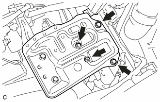
REMOVE CYLINDER BLOCK SIDE COVER
-
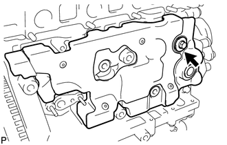
Remove the bolt, washer plate and cylinder block side cover.
-
-
REMOVE CRANK POSITION SENSOR
-
REMOVE CLUTCH COVER ASSEMBLY (for Manual Transaxle)
-
REMOVE CLUTCH COVER ASSEMBLY (for Multi-Mode Manual Transaxle)
-
REMOVE CLUTCH DISC ASSEMBLY (for Manual Transaxle)
-
REMOVE CLUTCH DISC ASSEMBLY (for Multi-Mode Manual Transaxle)
-
REMOVE FLYWHEEL SUB-ASSEMBLY
-
REMOVE NO. 1 CRANKSHAFT POSITION SENSOR PLATE
-
INSTALL ENGINE TO ENGINE STAND
-
Install the engine assembly to an engine stand.
-