CAMSHAFT(w/ Glow Plug Controller) REMOVAL
PROCEDURE
-
INSTALL ENGINE TO ENGINE STAND
-
REMOVE ENGINE COVER BRACKET
-
REMOVE GENERATOR ASSEMBLY
-
REMOVE GENERATOR BRACKET
-
REMOVE EGR WITH COOLER PIPE ASSEMBLY
-
REMOVE NO. 1 EGR COOLER BRACKET
-
REMOVE HARNESS BRACKET (for LHD)
-
REMOVE HARNESS BRACKET (for RHD)
-
REMOVE EGR VALVE (ELECTRIC EGR CONTROL VALVE ASSEMBLY)
-
REMOVE ENGINE OIL LEVEL DIPSTICK
-
REMOVE ENGINE OIL LEVEL DIPSTICK GUIDE
-
REMOVE INTAKE AIR CONNECTOR WITH DIESEL THROTTLE BODY
-
DISCONNECT NOZZLE LEAKAGE PIPE ASSEMBLY
-
REMOVE FUEL INLET PIPE SUB-ASSEMBLY
-
DISCONNECT NO. 1 FUEL HOSE
-
DISCONNECT NO. 2 FUEL HOSE
-
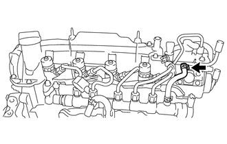
Slide the hose clip and disconnect the No. 2 fuel hose from the No. 2 nozzle leakage pipe.
-
-
REMOVE NO. 2 NOZZLE LEAKAGE PIPE
-
REMOVE FUEL PUMP PROTECTOR
-
REMOVE SUPPLY PUMP ASSEMBLY
-
REMOVE NO. 2 OIL COOLER HOSE
-
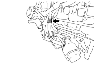
REMOVE NO. 4 WATER BY-PASS HOSE
-
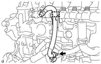
Disengage the clamp to separate the No. 4 water by-pass hose from the common rail assembly.
-
Slide the hose clip and remove the No. 4 water by-pass hose from the water inlet pipe.
-
-
REMOVE WATER BY-PASS PIPE SUB-ASSEMBLY
-
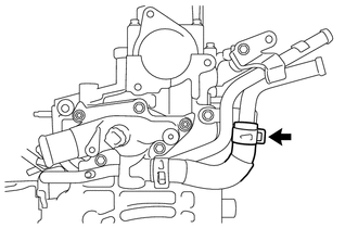
Slide the hose clip and disconnect the No. 6 water by-pass hose from the water by-pass pipe sub-assembly.
-
Slide the hose clip and disconnect the water by-pass hose from the tube connector.
-
Slide the hose clip and disconnect the oil cooler hose from the water by-pass pipe sub-assembly.
-
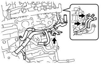
Remove the 3 bolts and water by-pass pipe sub-assembly from the No. 2 turbocharger stay, cylinder head sub-assembly, cylinder block sub-assembly and water inlet housing.
-
Remove the O-ring from the water by-pass pipe sub-assembly.
-
-
REMOVE VACUUM PUMP ASSEMBLY
-
REMOVE V-RIBBED BELT TENSIONER ASSEMBLY
-
REMOVE CYLINDER HEAD COVER SUB-ASSEMBLY
-
REMOVE ENGINE MOUNTING BRACKET RH
-
REMOVE NO. 2 TIMING CHAIN COVER
-
REMOVE CAMSHAFT POSITION SENSOR
-
REMOVE CRANKSHAFT DAMPER SUB-ASSEMBLY
-
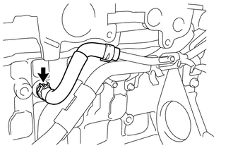
DISCONNECT WATER INLET HOSE LH
-
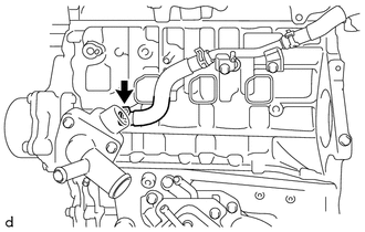
Slide the hose clip and disconnect the water inlet hose LH from the water inlet.
-
-
REMOVE TIMING CHAIN COVER SUB-ASSEMBLY
-
REMOVE TIMING CHAIN COVER OIL SEAL
-
REMOVE NO. 1 CHAIN TENSIONER ASSEMBLY
-
REMOVE CHAIN TENSIONER SLIPPER
-
REMOVE NO. 1 CHAIN VIBRATION DAMPER
-
REMOVE CHAIN SUB-ASSEMBLY
-
REMOVE CAMSHAFT
-
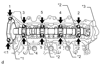
*1 No. 1 Camshaft Bearing Cap *2 No. 2 Camshaft Bearing Cap *3 No. 3 Camshaft Bearing Cap *4 No. 4 Camshaft Bearing Cap Remove the 10 bolts from the No. 1 camshaft bearing cap, 3 No. 2 camshaft bearing caps and No. 4 camshaft bearing cap by loosening them in the order shown in the illustration, and then remove the No. 1 camshaft bearing cap, 3 No. 2 camshaft bearing caps and No. 4 camshaft bearing cap from the cylinder head sub-assembly.
Note
-
Using several steps, uniformly loosen the bolts while keeping the camshaft level.
-
Do not remove the No. 3 camshaft bearing cap.
-
-
Remove the camshaft from the cylinder head sub-assembly.
-